Magnet assembly capable of generating magnetic field having direction that is uniform and can be changed and sputtering apparatus using the same

Inactive Publication Date: 2009-03-26
CANON ANELVA CORP
View PDF8 Cites 7 Cited by
  • Summary
  • Abstract
  • Description
  • Claims
  • Application Information

AI Technical Summary

Benefits of technology

[0019]The magnet assembly of the present invention enables a magnetic field of a uniform direction to be formed on a substrate surface of 5 inches to 12 inches in diameter or of larger sizes. Because of the feature that the direction of a magnetic field is reversed by rotating only the dipole magnet subassembly, a mechanism for rotating the whole assembly becomes unnecessary. Also, because it is unnecessary to use an electr

Problems solved by technology

Such annealing treatment, however, may sometimes cause diffusion in a metal film, changes in crystal structure, and damage a resist film with a low allowable temperature limit.
Therefore, a rotary mechanism for this purpose is necessary and this makes the sputtering apparatus complex, resulting in a cost increase.
Howe

Method used


Image

  • Magnet assembly capable of generating magnetic field having direction that is uniform and can be changed and sputtering apparatus using the same
  • Magnet assembly capable of generating magnetic field having direction that is uniform and can be changed and sputtering apparatus using the same
  • Magnet assembly capable of generating magnetic field having direction that is uniform and can be changed and sputtering apparatus using the same

Examples


Embodiment Construction

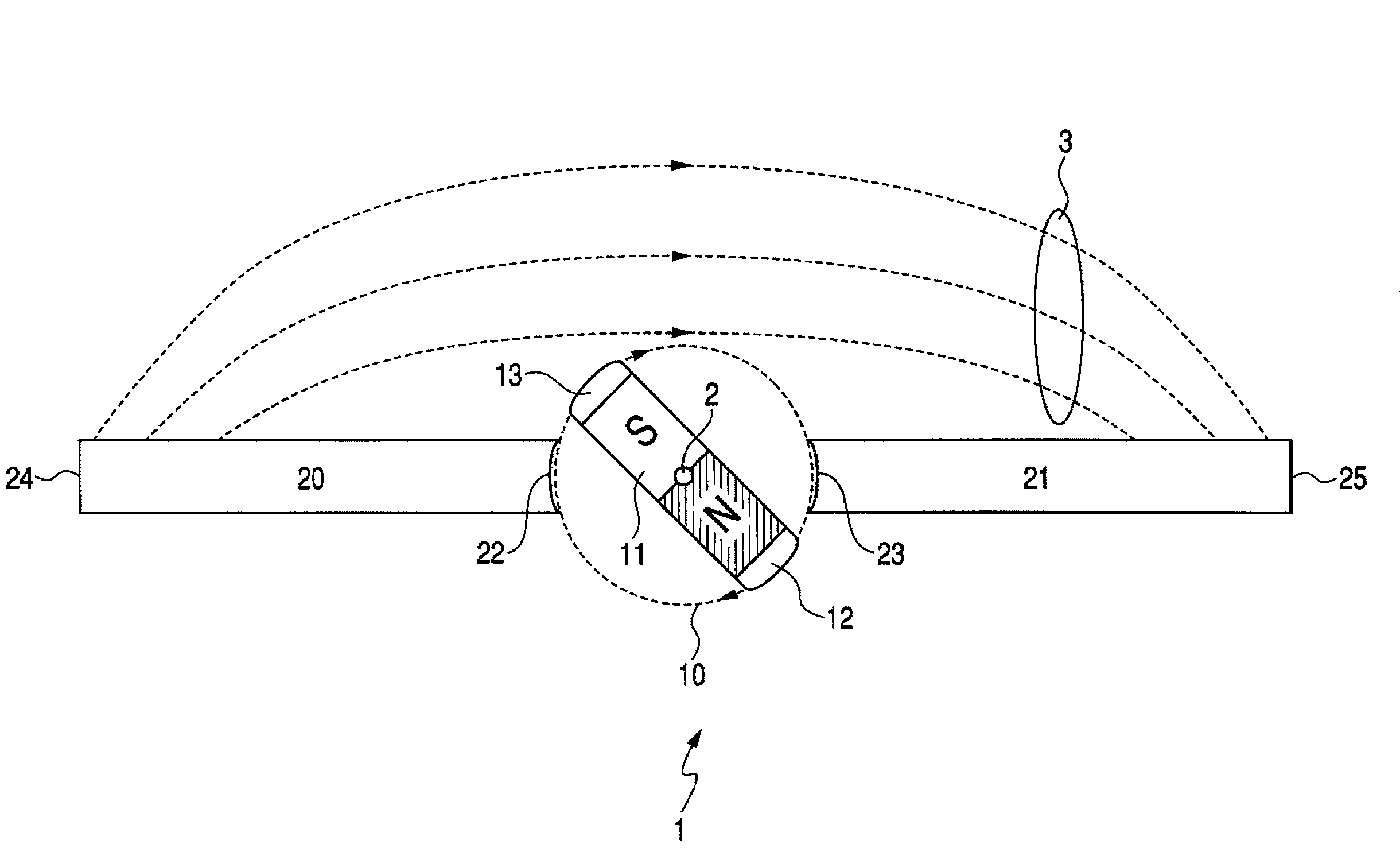
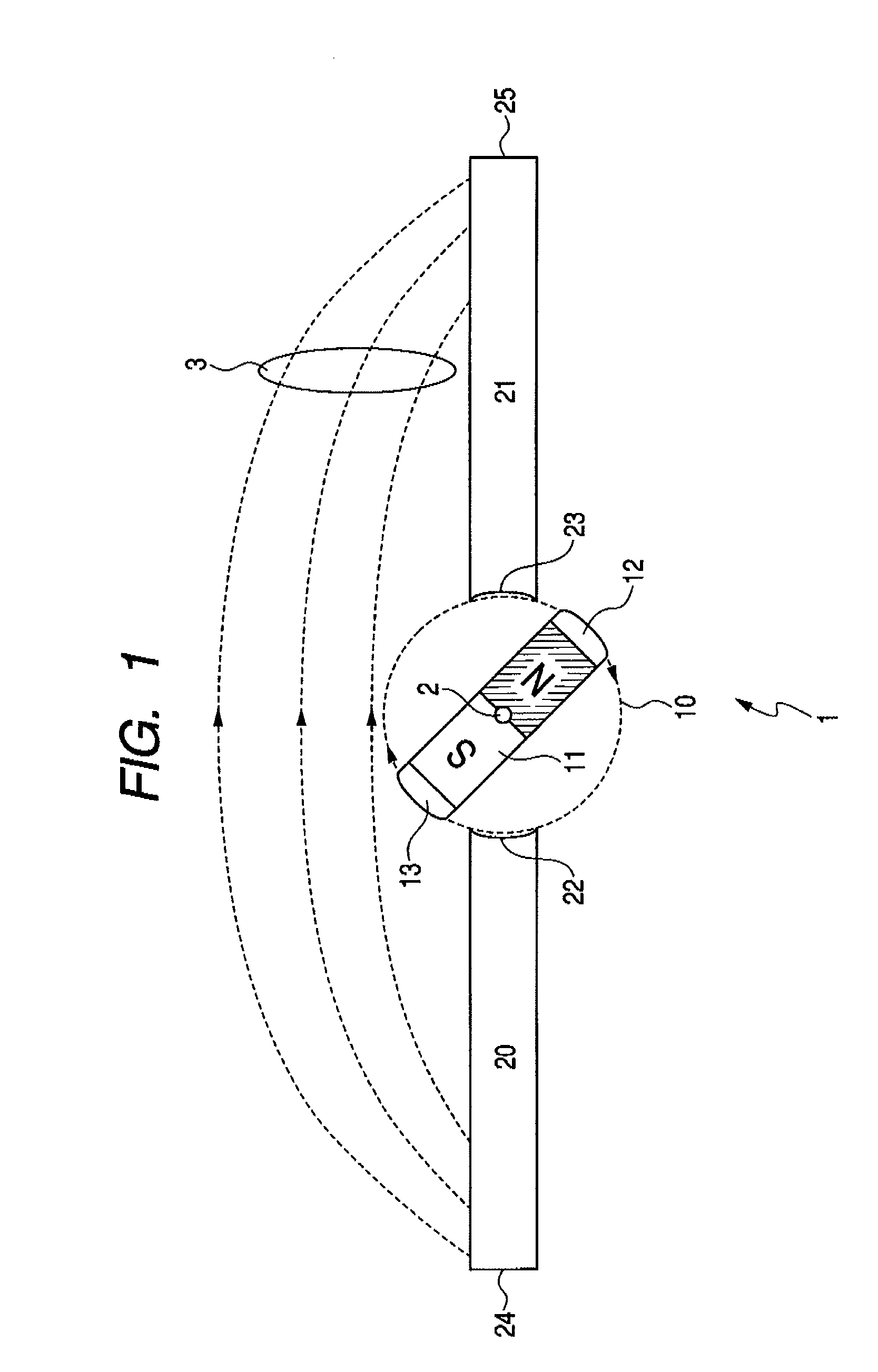
[0059]FIG. 1 is a diagram showing the construction of a magnet assembly 1 related to an embodiment of the present invention. The magnet assembly 1 comprises a dipole magnet subassembly (a partially assembled part) 10 capable of rotating around a shaft 2 perpendicular to the sheet surface and at least two flux guide subassemblies 20 and 21.

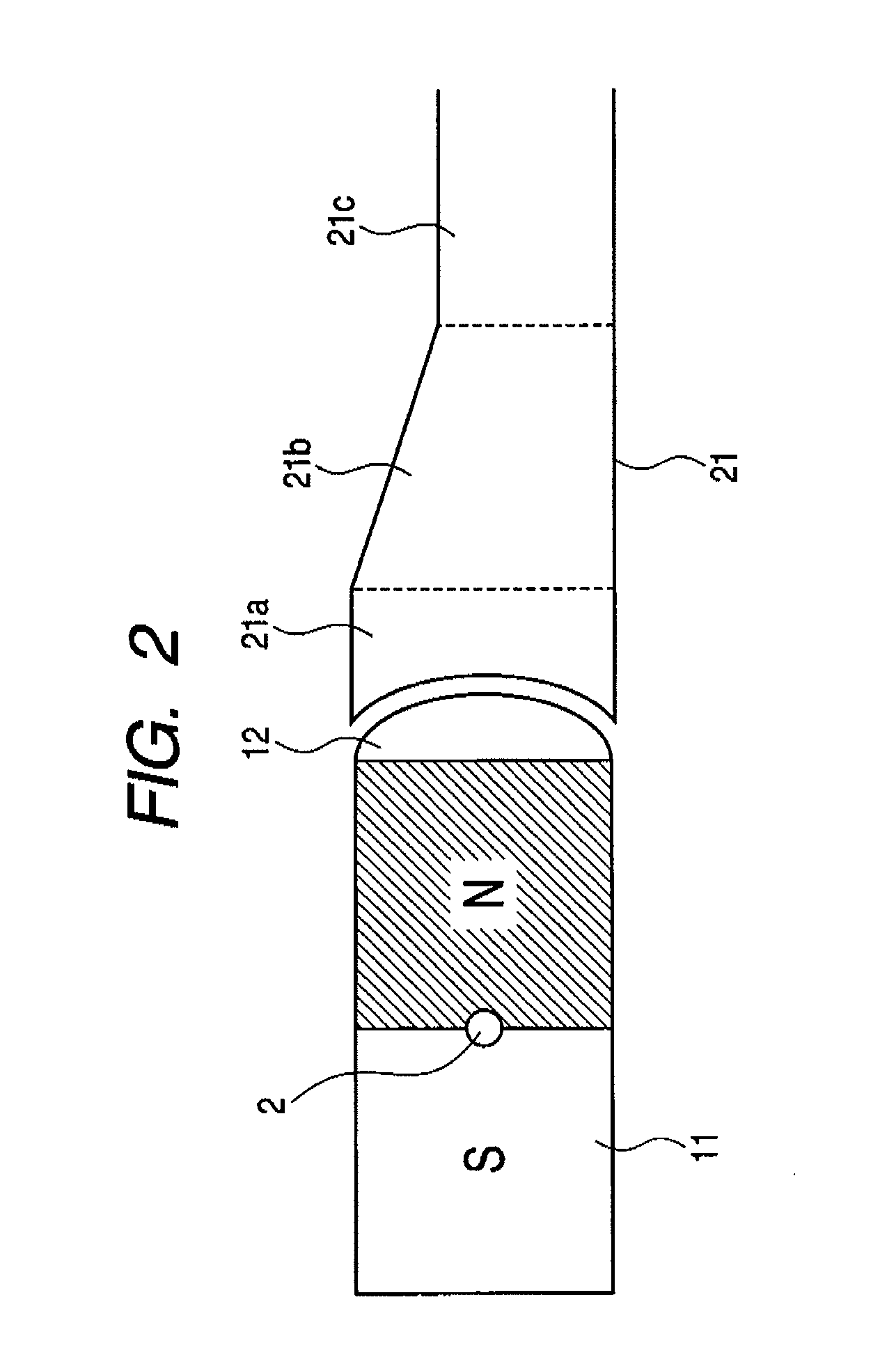
[0060]The dipole magnet subassembly 10 comprises at least one permanent magnet 11 and two magnetically permeable end portions 12 and 13, which are provided for each permanent magnet. The magnetically permeable end portions 12 and 13 have convex end portions. The permanent magnet 11 preferably has the shape of a bar or the shape of a square, and may be formed from a plurality of magnets having the same length. The plurality of magnets may include magnets having different magnetic forces. In this case, a magnet of a stronger magnetic force can be disposed nearer to the end portion of the permanent magnet 11 in order to improve uniformity of magnetic ...


PUM

PropertyMeasurementUnit
Angleaaaaaaaaaa
Lengthaaaaaaaaaa
Thicknessaaaaaaaaaa

Abstract

The magnet assembly includes one rotatable dipole magnet subassembly, which is formed from a permanent magnet and a magnetically permeable convex end portion coupled to each of both ends of the permanent magnet, and at least two magnetically permeable flux guide subassemblies, which are configured so as to be magnetically coupled to the dipole magnet subassembly. The flux guide subassembly has a concave end portion that fits into the convex end portion. The flux guide assemblies guide a flux from the dipole magnet subassembly and generate a flux outside. The condition of fitting into the flux guide subassemblies is reversed by rotating the dipole magnet subassembly, whereby it is possible to easily reverse the direction of a magnetic field generated outside.

Description

TECHNICAL FIELD[0001]The present invention relates to a magnet assembly capable of generating a magnetic field with a uniform and variable direction and a sputtering apparatus that forms a thin film on a substrate using the magnet assembly. More specifically, the present invention relates to a magnet assembly that can change the direction of a magnetic field generated by permanent magnets in a rotatable dipole magnet subassembly, and a sputtering apparatus for forming a thin film of a soft magnetic material having a magnetic anisotropy set in the same direction over a substrate using the magnet assembly.BACKGROUND ART[0002]A soft magnetic layer having a high-moment magnetic anisotropy is required for write heads for magnetic recording storage and magnetoresistive random access memory (MRAM). Also, for example, in the field of magnetoresistive sensors and the like, it is necessary to perform annealing treatment in a magnetic field with a uniform direction in order to obtain a magneti...

Claims


Application Information

Patent Timeline
IPC IPC(8): H01F7/02C23C14/35
CPCH01F7/0284H01J37/3461H01J37/3455H01J37/3408
Inventor ABARRA, EINSTEIN NOELENDO, TETSUYA
Owner CANON ANELVA CORP
Why Eureka
Try Eureka