Method for data exchange between military aircraft and device for carrying out this method

Active Publication Date: 2009-03-26
AIRBUS DEFENCE & SPACE
View PDF13 Cites 12 Cited by
  • Summary
  • Abstract
  • Description
  • Claims
  • Application Information

AI Technical Summary

Benefits of technology

[0013]An aspect of the present invention is to provide a method or a device with which a user data transmission between military aircraft takes place in a manner in w

Problems solved by technology

Moreover, transmission with omnidirectional characteristics can be realized only with high-energy expenditure.
This results in a very unfavorable ratio between the locatability range and the transmission range.
Since the radiation is also emitted essentially in the azimuth range, and thus only a small antenna surface is available on the aircraft, these di

Method used


Image

  • Method for data exchange between military aircraft and device for carrying out this method
  • Method for data exchange between military aircraft and device for carrying out this method
  • Method for data exchange between military aircraft and device for carrying out this method

Examples


Example

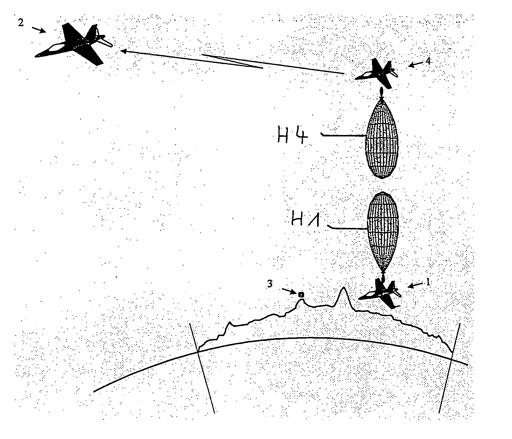
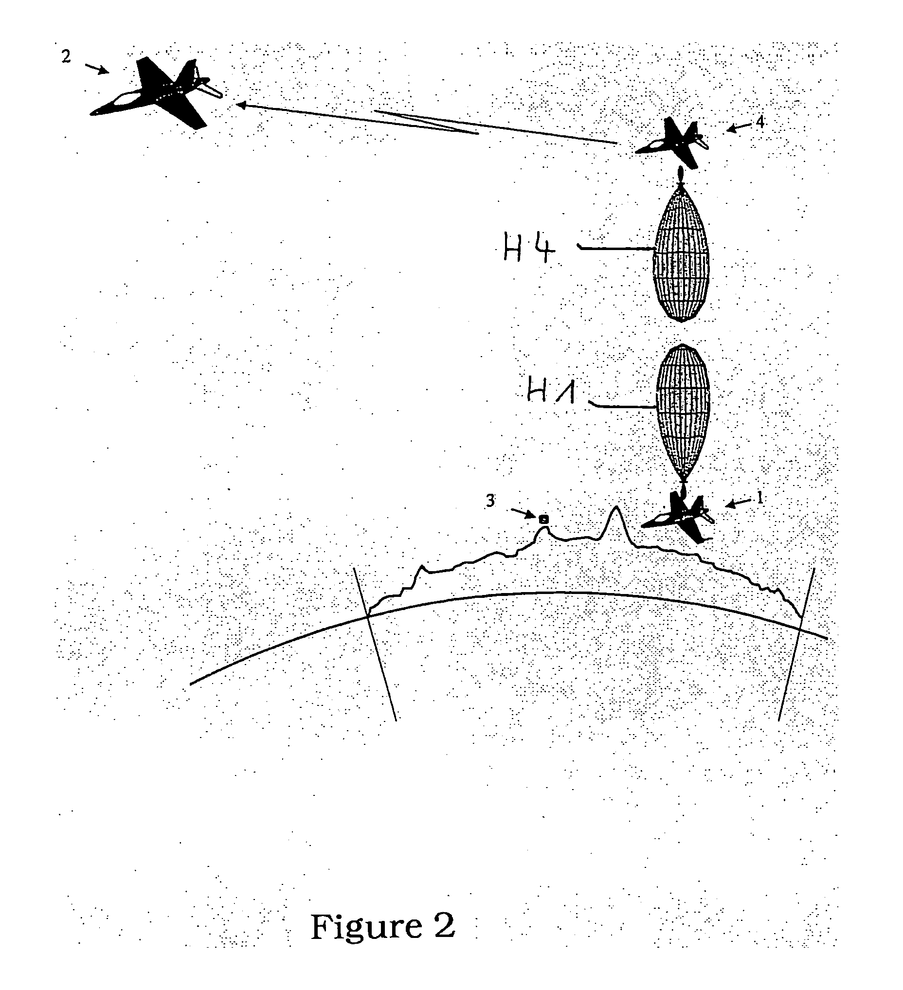
[0032]FIG. 2 diagrammatically shows a constellation of a low-flying transmitting aircraft 1 and a high-flying receiving aircraft 2, and a locating station 3 to be regarded as hostile with respect to the aircraft shown. According to the present invention, an additional relatively high-flying relay aircraft 4 is provided for the user data exchange according to the present invention, which aircraft receives user data from the lower flying aircraft 1 and retransmits the user data to the aircraft 2 provided for reception. During the user data transmission, the flight altitude of the relay aircraft 4 is greater than the flight altitude of the low-flying aircraft 1. The antenna main lobe H1 produced by the corresponding system of the relatively low-flying transmitting aircraft 1 is thereby oriented according to the present invention within an opening lobe of a maximum of 30° vertically to the earth's surface upwards to the relay aircraft 4. With an antenna main lobe H4 according to the pre...


PUM


Abstract

A device for user data transmission implemented in an aircraft for transmitting user data to a relay aircraft. The device includes a controllable directional antenna arrangement and an antenna steering module that is structured and arranged to control radiation properties and transmitting power of the antenna arrangement. Moreover, the device includes an antenna orientation module and a threat management system. Additionally, the device includes an optimization device. Furthermore, the threat management system and the optimization device are associated with the antenna steering module and the optimization device receives a desired radiation profile from the threat management system and a desired direction range of an antenna lobe from the antenna orientation module. The instant abstract is neither intended to define the invention disclosed in this specification nor intended to limit the scope of the invention in any way.

Description

CROSS-REFERENCE TO RELATED APPLICATIONS[0001]The present application is a Continuation of International Application No. PCT / DE03 / 01358, filed Apr. 25, 2003 and claims priority of German Patent Application No. 102 19 023.2, filed on Apr. 27, 2002. Moreover, the disclosure of International Patent Application No. PCT / DE03 / 01358 filed Apr. 25, 2003 is expressly incorporated by reference herein in its entirety.BACKGROUND OF THE INVENTION[0002]1. Field of the Invention[0003]The present invention relates to a method for the transmission of user data between military aircraft via antennas with controllable directional effect and a device for carrying out the method.[0004]2. Discussion of Background Information[0005]With data exchange between military aircraft, it is of the greatest importance that they are not discovered in an environment threatened by enemy reconnaissance systems. Military aircraft have been hitherto equipped for data transmission with omnidirectional antennas that essenti...

Claims


Application Information

Patent Timeline
IPC IPC(8): H04B7/00H01Q3/24H01Q3/26H01Q25/00
CPCH01Q3/24H04B7/18506H01Q25/00H01Q3/26
Inventor HURST, PETERMEHLTRETTER, LUDWIGWERTH, MONIKA VON DER
Owner AIRBUS DEFENCE & SPACE
Why Eureka
Try Eureka