
Deposition apparatus for temperature sensitive materials

a technology of deposition apparatus and temperature sensitive materials, which is applied in the direction of vacuum evaporation coating, chemical vapor deposition coating, coating, etc., can solve the problems of significant degradation, changes in the structure of molecules and associated changes in material properties, and the use of organic materials in the manufacture of oled devices are often subject to degradation, so as to reduce costs and improve the control of deposition rate

Inactive Publication Date: 2009-03-26
GLOBAL OLED TECH
View PDF0 Cites 22 Cited by
  • Summary
  • Abstract
  • Description
  • Claims
  • Application Information

AI Technical Summary

Benefits of technology

[0014]It is an advantage of the present invention that a deposition system for depositing a plurality of thin films on a substrate can use deposition apparatus in a variety of orientations. Such a design provides reduced costs and improved deposition rate control.
that a deposition system for depositing a plurality of thin films on a substrate can use deposition apparatus in a variety of orientations. Such a design provides reduced costs and improved deposition rate control.

Problems solved by technology

The organic materials used in the manufacture of OLED devices are often subject to degradation when maintained at or near the desired rate-dependent vaporization temperature for extended periods of time.
Exposure of sensitive organic materials to higher temperatures can cause changes in the structure of the molecules and associated changes in material properties.
In this manner, the material is consumed before it has reached the temperature exposure threshold to cause significant degradation.
The limitations with this practice are that the available vaporization rate is very low due to the limitation on heater temperature, and the operation time of the source is very short due to the small quantity of material present in the source.
The low deposition rate and frequent source recharging place substantial limitations on the throughput of OLED manufacturing facilities.
A secondary consequence of heating the entire organic material charge to roughly the same temperature is that it is impractical to mix additional organic materials, such as dopants, with a host material unless the vaporization behavior and vapor pressure of the dopant is very close to that of the host material.
This is generally not the case and, as a result, prior art devices frequently require the use of separate sources to co-deposit host and dopant materials.
A small change in source temperature leads to a very large change in vaporization rate.
Despite this, prior-art devices employ source temperature as the only way to control vaporization rate.
These measures have the desired effect on steady-state vaporization rate stability but have a detrimental effect at start-up.
A further limitation of prior-art sources is that the geometry of the vapor manifold changes as the organic material charge is consumed.
Moreover, the structural design of prior-art sources limits the orientation of the vapor plumes.
This in turn reduces the variety of deposition systems to which the prior-art sources may be applied.
If the material is not held within the chamber such that the sublimating top surface is physically above the remainder of the material, the sublimated material will not form a well-controlled plume and material may even fall out of the chamber.
Hence, the geometry of the prior-art sources limits the vapor plume orientation.
However, neither of these designs can be used in alternative orientations and are therefore limited in their applicability.
However, no design may be used in more than one orientation and rely on gravity to provide a suitable material surface for sublimation.

Method used


Image

  • Deposition apparatus for temperature sensitive materials
  • Deposition apparatus for temperature sensitive materials
  • Deposition apparatus for temperature sensitive materials

Examples


Embodiment Construction

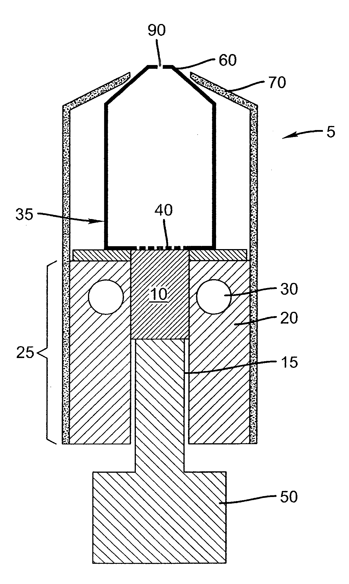
[0035]A system for the deposition of vaporized materials on a substrate includes two or more orientation-independent material vaporization and deposition apparatuses for directing vaporized organic materials onto a substrate surface to form two or more thin-films. Each of the orientation-independent apparatuses are arranged in a different relative orientation and comprise: a chamber containing a quantity of material; a permeable member at one end of the chamber with a heating element for vaporizing the material; and means for continuously feeding the material toward the permeable member as it is vaporized, whereby organic material vaporizes at a desired rate-dependent vaporization temperature at the one end of the chamber. A variety of means for continuously feeding the material may be employed, for example, a piston, an auger, an impeller, a nozzle either working independently or in combination with one another, or any other powder metering device.

[0036]Turning now to FIG. 1, there...


PUM

PropertyMeasurementUnit
Flexibilityaaaaaaaaaa
Sensitivityaaaaaaaaaa
Boiling pointaaaaaaaaaa

Abstract

A system for the deposition of vaporized materials on a substrate is described, comprising at least first and second orientation-independent apparatuses for directing vaporized organic materials onto a substrate surface to form first and second films, each of the first and second orientation-independent apparatuses being arranged in a different relative orientation and comprising: a chamber containing a quantity of material; a permeable member at one end of the chamber with a heating element for vaporizing the material; and means for continuously feeding the material toward the permeable member as it is vaporized, whereby organic material vaporizes at a desired rate-dependent vaporization temperature at the one end of the chamber. A plurality of thin films may be deposited on a substrate using deposition apparatus in a variety of orientations. Such a design provides reduced costs and improved deposition rate control.

Description

FIELD OF THE INVENTION[0001]The present invention relates to the field of physical vapor deposition where a source material is heated to a temperature so as to cause vaporization and produce a vapor plume to form a thin film on a surface of a substrate.BACKGROUND OF THE INVENTION[0002]An OLED device includes a substrate, an anode, a hole-transporting layer made of an organic compound, an organic luminescent layer with suitable dopants, an organic electron-transporting layer, and a cathode. OLED devices are attractive because of their low driving voltage, high luminance, wide-angle viewing and capability for full-color flat emission displays. Tang et al. described this multilayer OLED device in their U.S. Pat. Nos. 4,769,292 and 4,885,211.[0003]Physical vapor deposition in a vacuum environment is the principal way of depositing thin organic material films as used in small molecule OLED devices. Such methods are well known, for example, Barr in U.S. Pat. No. 2,447,789 and Tanabe et al...

Claims


Application Information

Patent Timeline
IPC IPC(8): C23C16/00
CPCC23C14/246C23C14/243
Inventor COK, RONALD S.LONG, MICHAEL
Owner GLOBAL OLED TECH
Learn More