Process for controlling an internal combustion engine

a technology of internal combustion engine and process, which is applied in the direction of electrical control, non-mechanical valves, instruments, etc., can solve the problems of high harbor docking fees, inability to interpret wear as allowable or not allowable, etc., and achieve the effect of improving operational reliability

Inactive Publication Date: 2009-03-26
MOTOREN UND TURBINEN UNION MUNCHEN GMBH
View PDF11 Cites 48 Cited by
  • Summary
  • Abstract
  • Description
  • Claims
  • Application Information

AI Technical Summary

Benefits of technology

[0004]The invention is based on the object of providing a process with improved operational reliability.
[0007]For example, increasing the power output of the internal combustion engine causes the temperature at the reciprocating gas valve to increase, which has the effect of decreasing the valve clearance, which can be allowable for this particular operating point. In this way it is also possible to tell with certainty how far the valve seat has worn down.
[0009]A key advantage of the process is that the maintenance of large diesel engines can be carried out on the basis of their actual condition. As a result of the elimination of the mechanical readjustments of valve clearance by the service mechanic, maintenance costs for the end user are significantly reduced. The model-based solution also offers the advantage that the process can be offered as a pure software solution in an upgrade package.

Problems solved by technology

In the case of a large diesel engine with sixteen valves, for example, this is a time-consuming and cost-intensive procedure and, if the engine is installed in a ship, it leads to correspondingly high harbor docking fees.
The critical point in these devices and methods is that, although the temperature-caused change in length of the reciprocating gas valve is in fact detected as a positional deviation, it cannot be interpreted as allowable or not allowable in the sense of wear.

Method used


Image

  • Process for controlling an internal combustion engine
  • Process for controlling an internal combustion engine
  • Process for controlling an internal combustion engine

Examples


Embodiment Construction

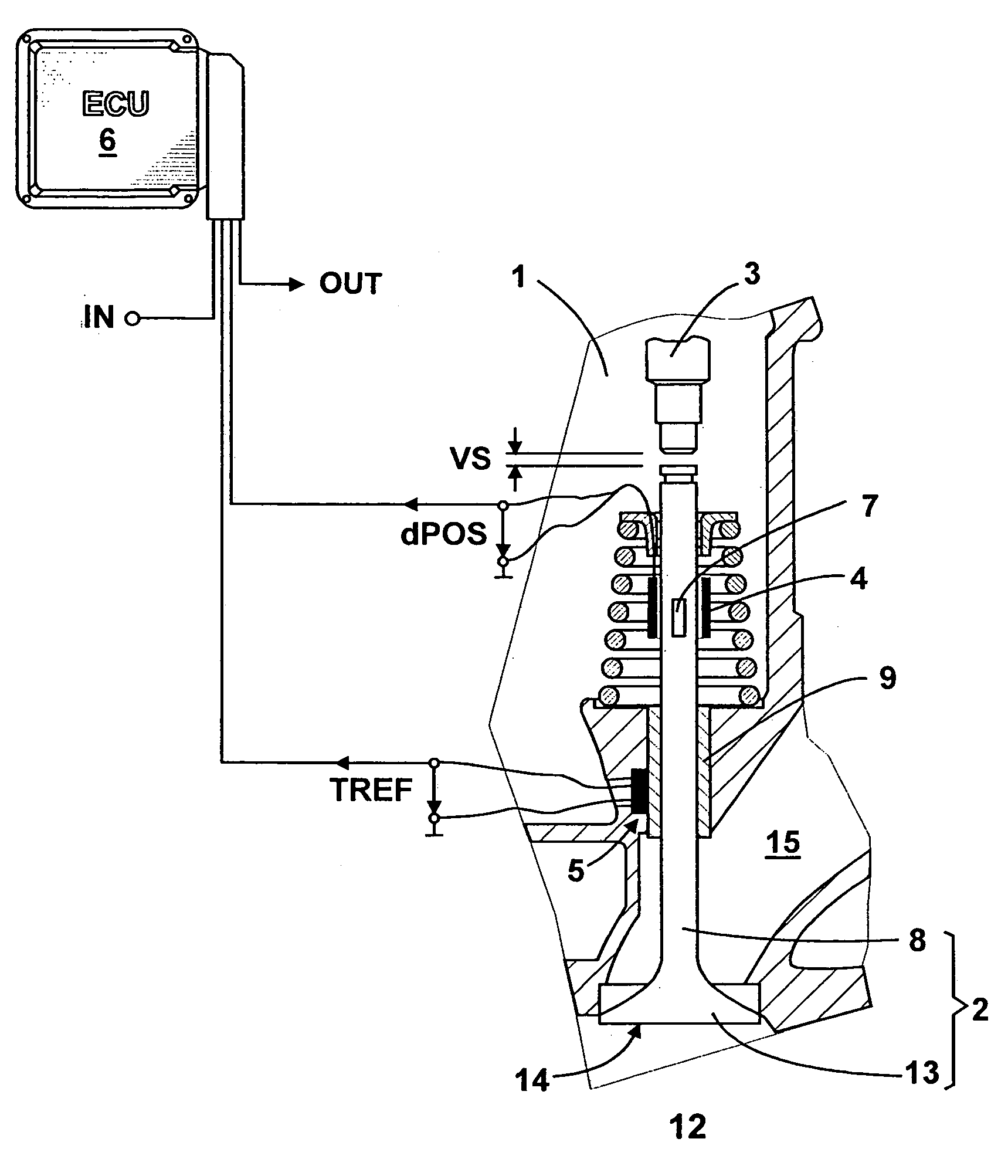
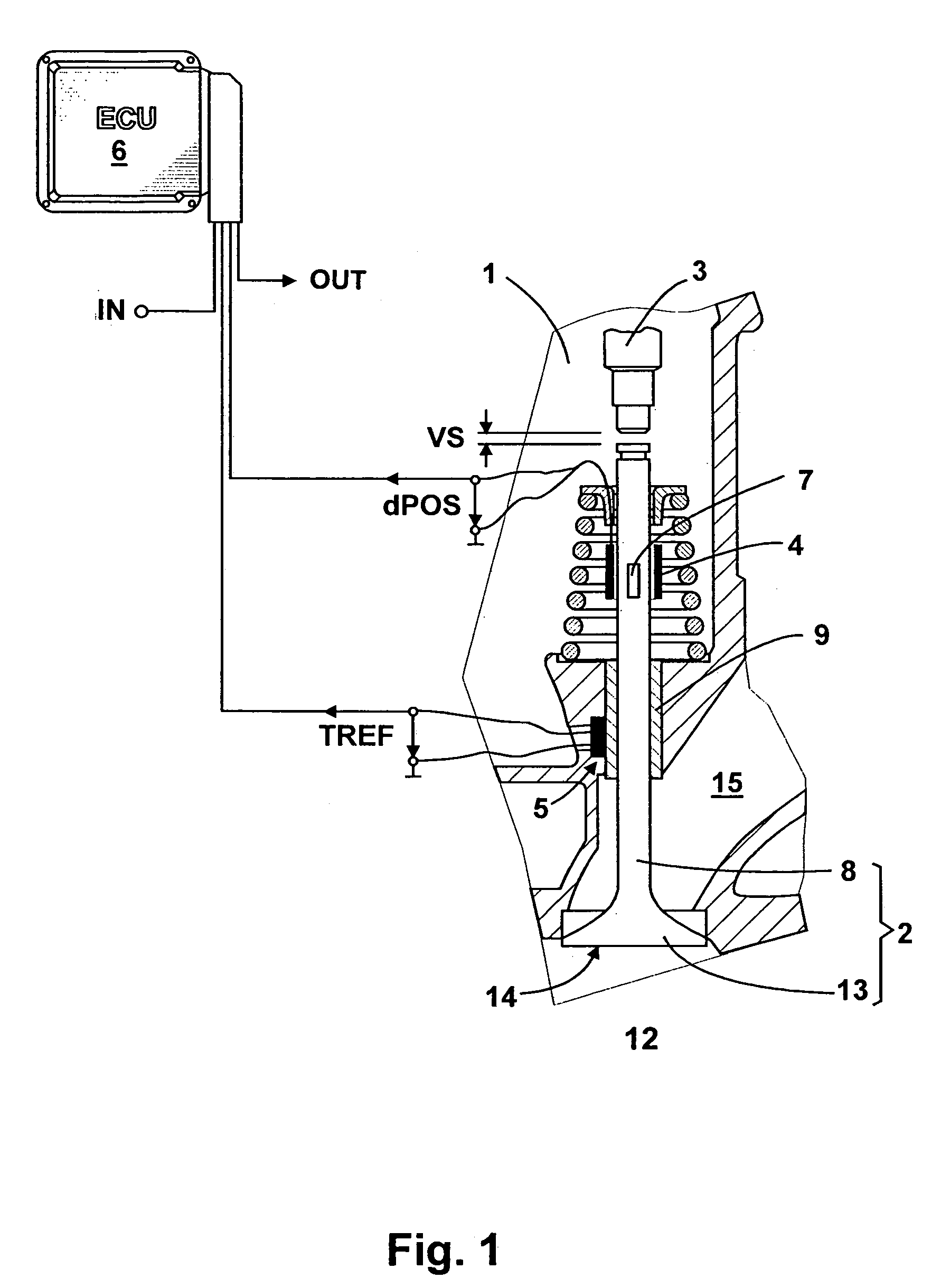
[0016]FIG. 1 shows a diagram of the system with a temperature sensor for measuring a reference temperature TREF. The individual components are: a cylinder head 1 with a reciprocating gas valve 2, such an intake valve; a rocker 3 for actuating the reciprocating gas valve 2; a position sensor 4; the temperature sensor 5; and an electronic control unit (ECU) (6). The reference symbol VS characterizes the valve clearance between the rocker 3 and the reciprocating gas valve 2. The position sensor 4 detects the actual position of the reciprocating gas valve 2 by means of an inductive or capacitive pickup, for example, or an opto-electronic device or a magnetically coded area 7 on the valve shaft 8. In the electronic control unit 6, a positional deviation is then calculated from the actual position and a zero position. It is assumed in the following discussion that the position sensor 4 comprises an integrated evaluation unit, which provides the positional deviation dPOS between the actual...


PUM


Abstract

A process for controlling an internal combustion engine, in which an actual position of a reciprocating gas valve is detected by a position sensor, a positional deviation is calculated from the actual position and a zero position, a total length change of the reciprocating gas valve is calculated as a function of the temperature of the reciprocating gas valve, a valve clearance of the reciprocating gas valve is determined from the positional deviation and the total length change, and the further operation of the internal combustion engine is determined on the basis of the valve clearance.

Description

BACKGROUND OF THE INVENTION[0001]The invention relates to a process for controlling an internal combustion engine.[0002]In practice, large diesel engines are delivered without automatic valve clearance compensation. After a fixed, predetermined period of operation, therefore, the valve clearance must be adjusted by a service mechanic according to a maintenance plan. The maintenance plan lists the boundary conditions such as an engine cooling water temperature of less than 40° C. and each of the individual steps. First, an engine-cranking device is attached; the cylinder head covers are removed; and the cranking device is used to close the reciprocating gas valves one after the other. In the closed state, a feeler gauge is then used to check the actual valve clearance of each valve. If this deviates from the nominal valve clearance, the service mechanic must adjust the actual valve clearance with an adjusting screw until the actual value clearance agrees with the nominal valve cleara...

Claims


Application Information

Patent Timeline
Patent Type & Authority Applications(United States)
IPC IPC(8): F02D45/00
CPCF01L2009/0498F01L2820/045Y02T10/40F02D2041/227F02D2041/228F02D41/22F01L2009/4098
Inventor FRANK, HOLGERHEHLE, MARCWILLMANN, MICHAEL
Owner MOTOREN UND TURBINEN UNION MUNCHEN GMBH
Why Eureka
Try Eureka