Ventilation member

a technology of ventilation members and vents, which is applied in the direction of electrical apparatus casings/cabinets/drawers, lighting and heating apparatus, separation processes, etc., can solve the problems of inability to easily achieve the increase of gas permeation quantity of ventilation members, inability to achieve further improvement, and inability to easily adopt the size change of ventilation members, etc., to achieve shorten the molding time of tubular parts, improve productivity, and save costs

Active Publication Date: 2009-04-02
NITTO DENKO CORP
View PDF14 Cites 46 Cited by
  • Summary
  • Abstract
  • Description
  • Claims
  • Application Information

AI Technical Summary

Benefits of technology

[0013]The cover part may include plural spacers that support the tubular part along the filter-end Opening in the attached state where the tubular part is fit inside the cover part. The plural spacers prevent the bottom portion of the cover part from contacting closely with the gas permeable filter entirely, so that one of the gaps formed between the bottom portion of the cover part and the gas permeable filter is secured. When configured in this manner, not only is it possible to protect the gas permeable filter from dust, water droplets, and a physical shock in a reliable manner with the cover part, but it is also possible to form a gap that servers as a gas passage between the cover part and the gas permeable filter. In addition, by providing the spacers that support the tubular part in a distributed manner, it is possible to utilize spaces between the respective spacers that are adjacent to each other as gas passages.
[0014]In a more preferable configuration, the body portion of the tubular part may include an inner body portion and an outer body portion that surrounds the inner body portion. Herein, assuming that the thickness direction of the gas permeable filter is an axis line direction, a side in the axis line direction on which the filter-end opening is located is a front side, and a side on which the connection-end opening is located is a rear side, then by configuring in such a manner that a front end portion of the inner body portion is retracted to a position in the rear of a front end portion of the outer body portion, it is possible to form the front end portion of the outer body portion as a thin filter-end opening to which the gas permeable filter is attached. Further, coupling portions formed integrally with the inner body portion and the outer body portion may be provided between these portions at plural points in a circumferential direction. Accordingly, gaps that open frontward in the axis line direction and communicate with the space inside the tube of the tubular part are defined between the respective coupling portions that are adjacent to each other. When configured in this manner, it is possible to form gaps between the inner body portion and the outer body portion while producing a change in opening area. Because this configuration in turn can shorten the molding time of the tubular part (to be more concrete, the cooling time), the cost saving derived from the enhanced productivity can be expected.
[0015]It is also possible to have a structure in which the inner body portion and the outer body portion are connected to each other directly along an entire circumference on the rear side in the axis line direction. When configured in this manner, it is possible to make the connection-end opening sufficiently thick, and the ventilation member can be attached to the device that needs ventilation in a reliable manner.
[0016]At least one of the cover part and the tubular part may include fixing pieces positioned at plural points in a circumferential direction between the tubular part and the side wall portion of the cover part in the attached state. Also, gaps functioning as gas passages that communicate with the exterior can be formed between the respective fixing pieces that are adjacent to each other, and relative positions of the cover part and the tubular part can be determined through elastic deformation of at least one of the tubular part and the fixing pieces. According to the fixing pieces as described above, not only can the cover part and the tubular part be fixed relatively with respect to each other with ease, but also gas passages can be formed naturally between the cover part and the tubular part.

Problems solved by technology

Increasing a gas permeation quantity of the ventilation members, however, is not readily achieved.
The bottleneck in a gas permeation quantity is a gas permeable filter that has large gas permeation resistance, but the gas permeable filter has been improved to the point that further improvement is difficult.
Size changing of the ventilation members, however, is not readily adopted, because it involves a design change at the other end (at the device end).

Method used


Image

  • Ventilation member
  • Ventilation member
  • Ventilation member

Examples


first embodiment

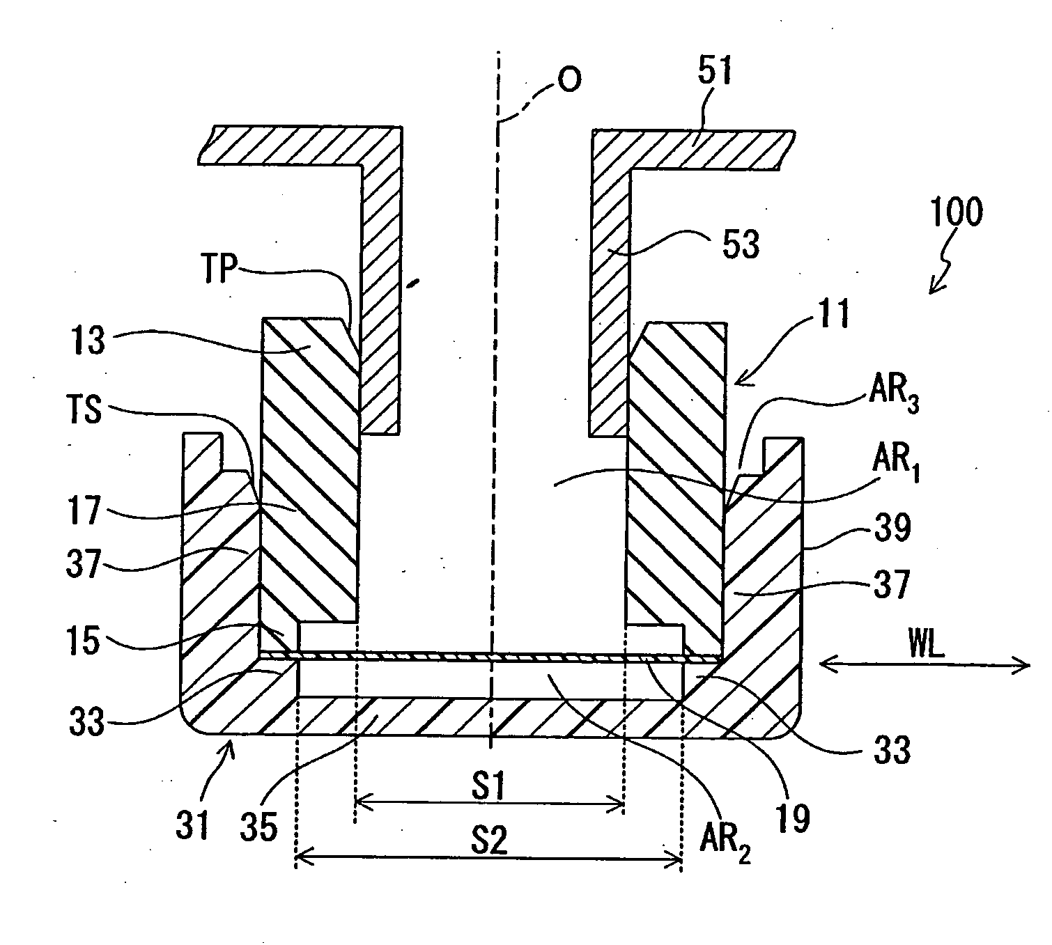
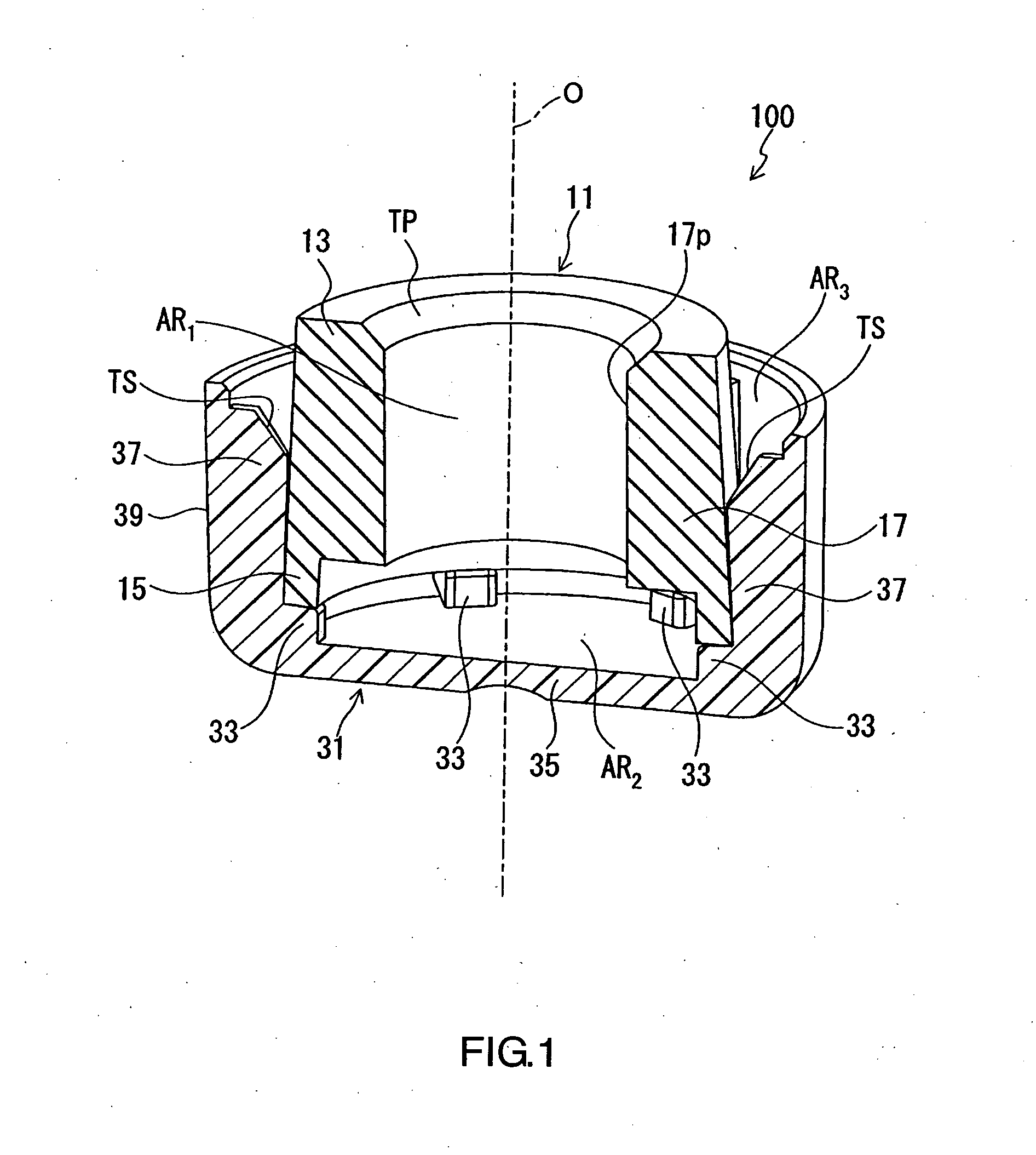
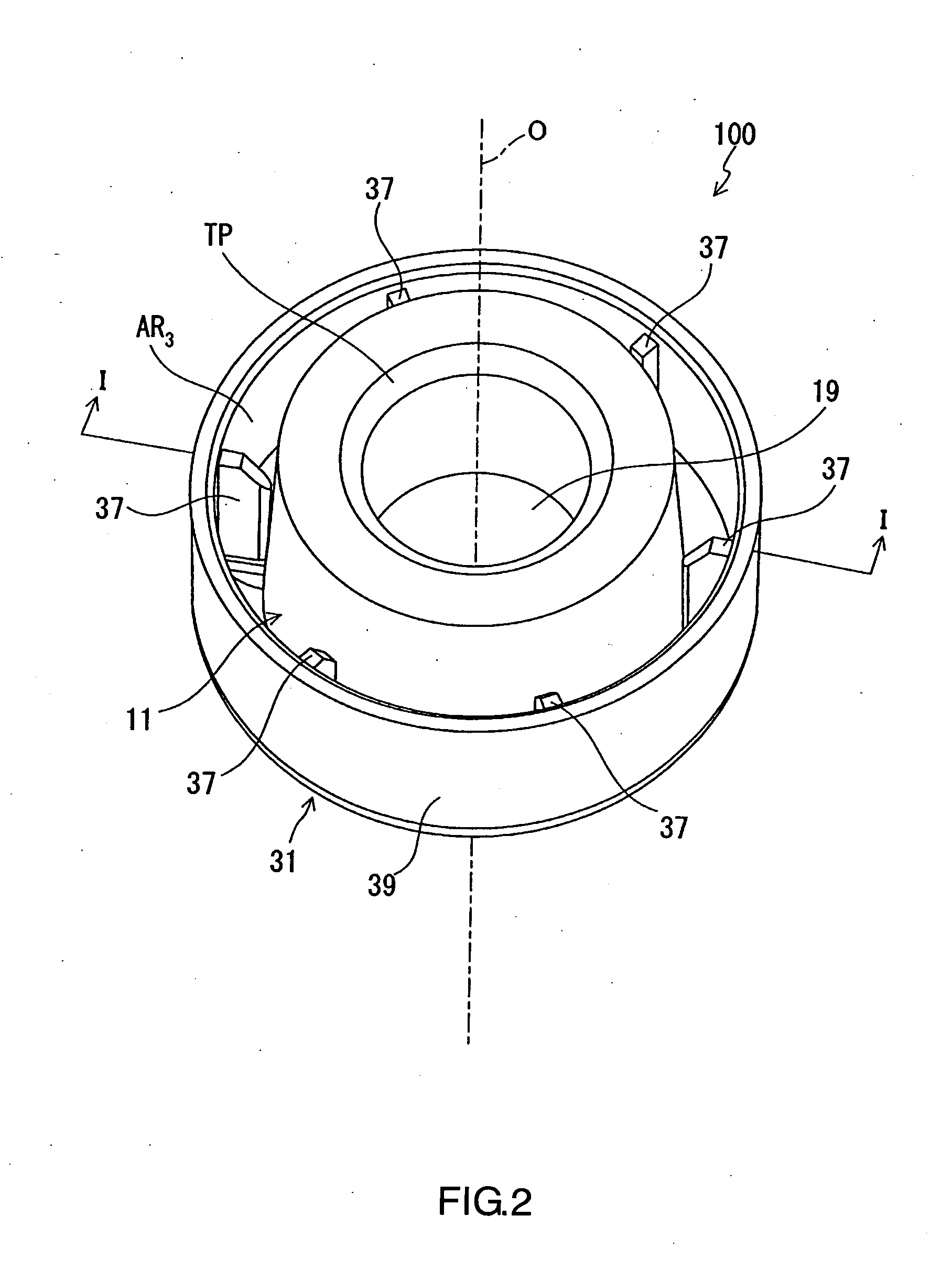
[0040]FIG. 1 is a sectional perspective view of a ventilation member of the invention. FIG. 2 is a perspective view of the ventilation member of FIG. 1. FIG. 3 is a cross section showing a state where the ventilation member of FIG. 1 and FIG. 2 is attached to the housing of a device that needs ventilation. As is shown in FIG. 3, by attaching a ventilation member 100 to a nozzle-like filter-attached portion 53 provided to a housing 51 of the device, it is possible to ventilate the interior of the housing 51 while preventing the entry of foreign matter, such as water droplets. In addition, it is possible to maintain the internal pressure of the housing 51 equal to the external pressure.

[0041]As shown in FIG. 1, FIG. 2, and FIG. 3, the ventilation member 100 includes a tubular part 11, a gas permeable filter 19, and a cover part 31. The gas permeable filter 19, however, is omitted in FIG. 1. The tubular part 11 is of an almost circular cylindrical shape and forms a gas passage AR1 that...

second embodiment

[0060]FIG. 9 is a sectional perspective view of a second embodiment of the ventilation member of the invention. FIG. 10 is a perspective view of the ventilation member of FIG. 9. The gas permeable filter 19, however, is omitted in FIG. 9. Applicable objects and the function of a ventilation member 200 of the second embodiment are the same as those of the ventilation member 100 described in the first embodiment above. The configuration is also common in that a gas permeation quantity per unit time is increased owing to the effective area of the gas permeable filter 19 that is enlarged by making the opening area of a filter-end opening 65 larger than the opening area of a connection-end opening 63. A major difference from the embodiment described above is that fixing pieces 97, which play a crucial role in determining the relative positions of a tubular part 61 and a cover part 81, are formed integrally with the tubular part 61.

[0061]As shown in FIG. 9 and FIG. 10, the ventilation mem...

third embodiment

[0067]FIG. 15 is an exploded perspective view of a third embodiment of the ventilation member of the invention. FIG. 16 is a longitudinal cross section of the ventilation member of FIG. 15.

[0068]As shown in FIG. 15 and FIG. 16, a ventilation member 300 includes a tubular part 102, a gas permeable filter 19, and a cover part 110. The tubular part 102 is of an almost circular cylindrical shape, and a first gas passage BR1 and second gas passages BR2 isolated from the first gas passage BR1 are formed in the interior thereof. The first gas passage BR1 is a gas passage that directly communicates with the interior space of the housing of a device. The second gas passages BR2 are gas passages that directly communicate with the exterior space of the housing of the device and the ventilation member 300. The cover part 110 is a part inside of which the tubular part 102 is fit. It is formed of a bottom portion 112 forming a gap TH between itself and the gas permeable filter 19, a side wall por...


PUM

PropertyMeasurementUnit
pore diameteraaaaaaaaaa
thicknessaaaaaaaaaa

Abstract

A ventilation member (100) of the invention includes a tubular part (11), a gas permeable filter (19), and a cover part (31). In an attached state where the tubular part (11) is fit into the cover part (31), gaps functioning as gas passages (AR2 and AR3) are formed between a bottom portion (35) of the cover part (31) and the gas permeable filter (19) and between a side wall portion (39) of the cover part (31) and a body portion (17) of the tubular part (11). The opening area (S2) of a filter-end opening (15) with respect to an in-plane direction (WL) perpendicular to the thickness direction of the gas permeable filter (19) is larger than the opening area (S1) of a connection-end opening (13) with respect to the in-plane direction (WL).

Description

TECHNICAL FIELD[0001]The present invention relates to a ventilation member that makes use of a gas permeable filter having gas permeability and waterproofness.BACKGROUND ART[0002]As described, for example, in JP10-085536A and JP2001-143524A, ventilation members used for automobile components (lamps, motors, sensors, switches, ECUs, and so forth) make use of a gas permeable filter (gas permeable membrane) having gas permeability, dustproofness, and waterproofness. Adaptation of such ventilation members to electrical devices, such as mobile communication devices, cameras, electric shavers, and electric toothbrushes, now is being discussed.[0003]The ventilation members as described above play a role of eliminating a pressure difference between the interior and the exterior of the device, propagating sounds, or discharging a gas generated inside the device while preventing the entry of dust or water into the interior of the device. For instance, fogging possibly occurs on a headlight of...

Claims


Application Information

Patent Timeline
Patent Type & Authority Applications(United States)
IPC IPC(8): F21V31/03
CPCF21S48/335B01D53/22B01D46/2414F21S45/30H05K5/0216B01D46/24B60R16/02B01D2279/35B01D53/88B01D46/2422B01D53/885H05K5/0213
Inventor FURUYAMA, SATORUYANAGI, TOSHIKI
Owner NITTO DENKO CORP
Why Eureka
Try Eureka