
Particulate filter

a technology of particle filter and particulate, which is applied in the direction of filtration separation, physical/chemical process catalyst, separation process, etc., can solve the problems of zr-based composite oxide being liable to be changed, reducing catalytic efficiency, etc., and achieves a higher burning rate, reduced catalytic efficiency, and high burning rate

Inactive Publication Date: 2009-04-02
MAZDA MOTOR CORP
View PDF13 Cites 10 Cited by
  • Summary
  • Abstract
  • Description
  • Claims
  • Application Information

AI Technical Summary

Benefits of technology

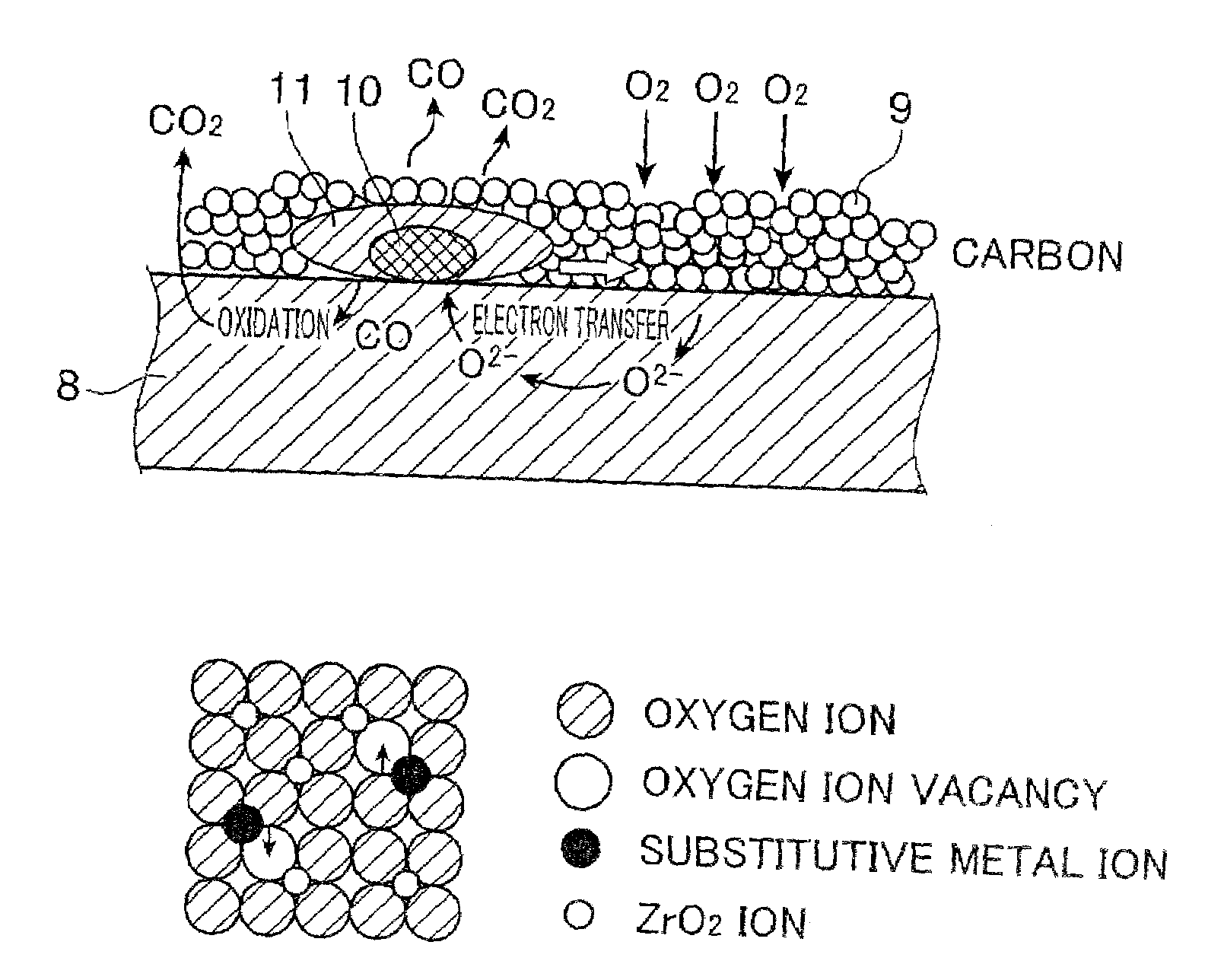
The present invention provides a particulate filter that can burn PM quickly. The filter has a catalyst layer made of a specific material, which allows for a higher PM burning rate. This results in improved fuel economy performance in engines that perform post-injection control. The filter has a porous partition wall with exhaust gas channels and a catalyst layer that contains a Zr-based composite oxide with a specific content ratio of non-cerium rare-earth metal to ZrO2. The slightly-changed crystal structure of the Zr-based composite oxide provides a higher PM burning rate.

Problems solved by technology

It was considered that, although a content ratio of an oxide of a rare-earth metal except cerium (the rare-earth metal except cerium will hereinafter be referred to as “non-cerium rare-earth metal”) in a Zr-based composite oxide included in a catalyst layer may be increased to obtain a higher PM burning rate, a crystal structure of the Zr-based composite oxide is liable to be changed, and consequently heat resistance deteriorates to cause a reduction in catalytic efficiency.

Method used


Image

  • Particulate filter
  • Particulate filter
  • Particulate filter

Examples


example

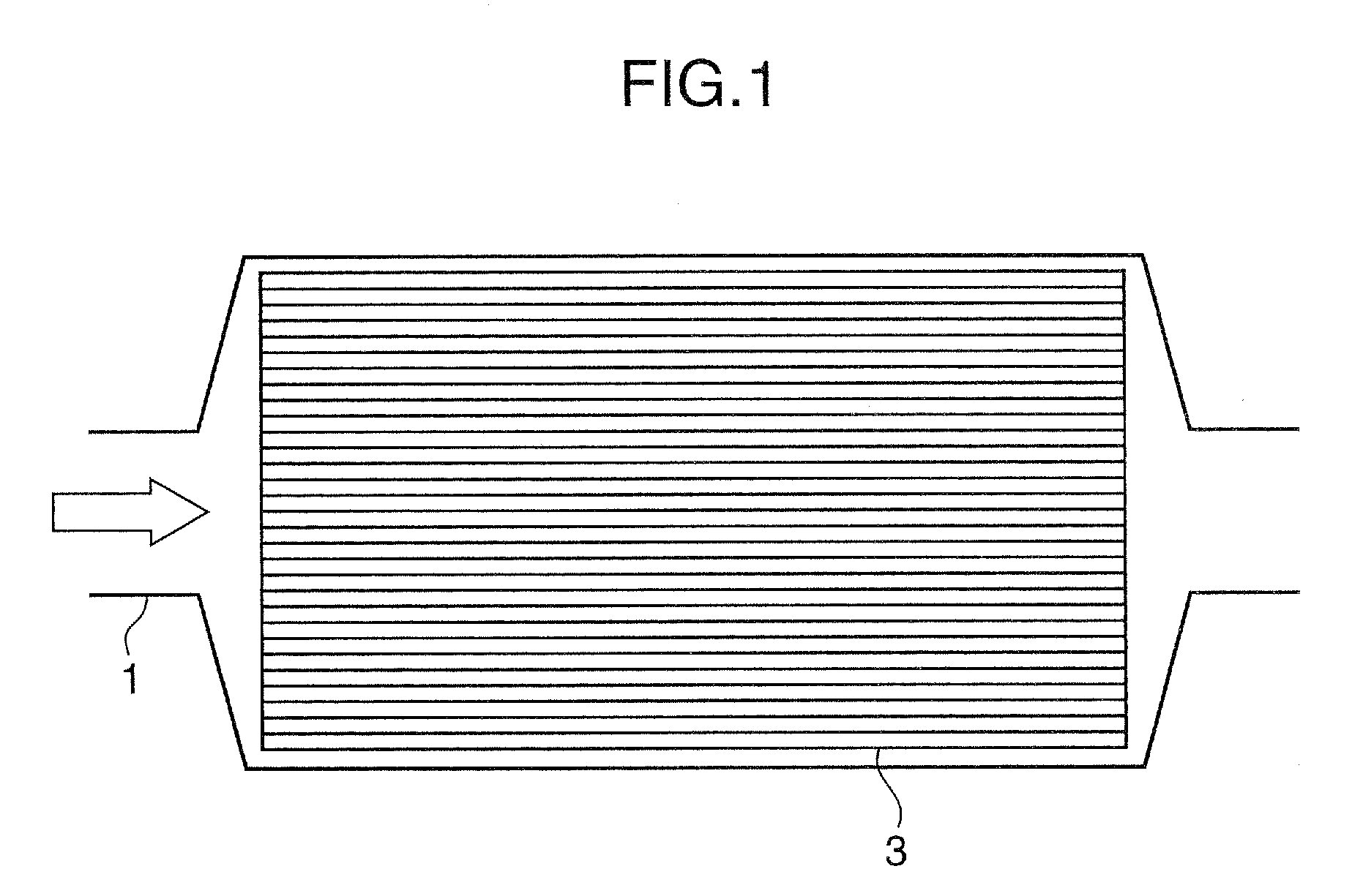
[0069]The present invention will be more specifically described based on Examples of the DPF 3 according to the above embodiment. It is understood that the present invention is not limited to the following Examples.

example a

[0070]An influence of a composition of a Zr-based composite oxide and / or a content ratio thereof on the PM burning rate was evaluated.

[0071]Firstly, a plurality of DPFs 3 different in a composition of a Zr-based composite oxide and / or a content ratio thereof were prepared in the following manner.

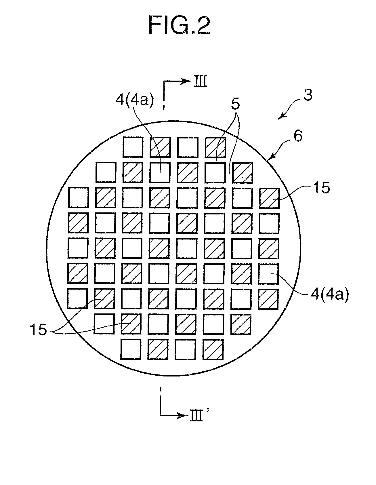
[0072]As a DPF substrate (filter body 6), a sample having a volume of 25 ml was cut out from a DPF substrate made of silicon carbide (SiC) and formed in a cell structure having a wall thickness (of a porous partition wall 5) of 12 mil, and a cell number of 300 cpsi (cells per square inch).

[0073]Then, a plurality of Zr-based composite oxides were prepared in such a manner as to have respective compositions and content ratios thereof as shown in Table 1. Each of the Zr-based composite oxides was obtained through a process of dissolving a given amount of a nitrate salt of each of required ones of a plurality of metal elements (Zr, Nd, Pr, La, etc.) in ion-exchanged water, dropping a basic solut...

example b

[0090]Further, the PM burning rate and others were evaluated using Zr-18Nd-18Pr and Zr-12Nd-18Pr.


PUM

PropertyMeasurementUnit
temperatureaaaaaaaaaa

Abstract

Disclosed is a particulate filter, which is adapted to be disposed in an exhaust passage of an engine to trap particulate matter contained in exhaust gas discharged from the engine. The particulate filter comprises a filter body having a porous partition wall which defines a plurality of exhaust gas channels allowing the exhaust gas to pass therethrough, and a catalyst layer formed on a surface of the porous partition wall. The catalyst layer includes a Zr-based composite oxide which contains zirconium (Zr), and a rare-earth metal except cerium, wherein a content ratio of an oxide of the non-cerium rare-earth metal to a total amount of ZrO2 and the oxide of the non-cerium rare-earth metal in the Zr-based composite oxide is set in the range of greater than 33 mol % to less than 40 mol %. The particulate filter of the present invention can achieve a higher PM burning rate to burn PM within a shorter period of time. In addition, the higher PM burning rate makes it possible to provide enhanced fuel economy performance in an engine designed to perform a post-injection control.

Description

BACKGROUND OF THE INVENTION[0001]1. Field of the Invention[0002]The present invention relates to a particulate filter for suppressing the emission of particulate matter contained in exhaust gas of an engine capable of a lean-burn operation, such as a diesel engine or a lean-burn gasoline engine.[0003]2. Background Art[0004]Exhaust gas from an engine capable of a lean-burn operation, such as a diesel engine or a lean-burn gasoline engine, contains therein particulate matter (PM) consisting primarily of carbonaceous components. With a view to reducing adverse environmental effects causes by the emission of such PM, a particulate filter is disposed in an exhaust passage of the engine to trap PM. The trapped PM will be gradually accumulated on the particulate filter in proportion to an operating time (engine operation time). Thus, the engine is designed to perform a control of burning the accumulated PM before an amount of accumulated PM reaches a predetermined value or more, to regener...

Claims


Application Information

Patent Timeline
Patent Type & Authority Applications(United States)
IPC IPC(8): B01D53/02
CPCB01D53/944Y02T10/22B01D2255/1021B01D2255/206B01D2255/20715B01D2255/407B01D2257/404B01D2257/702B01D2258/012B01J23/002B01J23/10B01J23/63B01J35/0006B01J37/0036B01J37/0201B01J37/024B01J37/0248B01J37/031B01J2523/00B01D53/945B01J2523/3725B01J2523/3787B01J2523/48B01J2523/35B01J2523/36B01J2523/3718B01J2523/3706B01J2523/3737Y02T10/12B01J35/19
Inventor YAMADA, HIROSHISUZUKI, KENJIHARADA, KOICHIROOKAMOTO, KENJITAKAMI, AKIHIDEMINEOI, SUSUMUSUMIDA, HIROSUKI
Owner MAZDA MOTOR CORP
Learn More