Drive apparatus for ultrasonic motor
- Summary
- Abstract
- Description
- Claims
- Application Information
AI Technical Summary
Benefits of technology
Problems solved by technology
Method used
Image
Examples
first embodiment
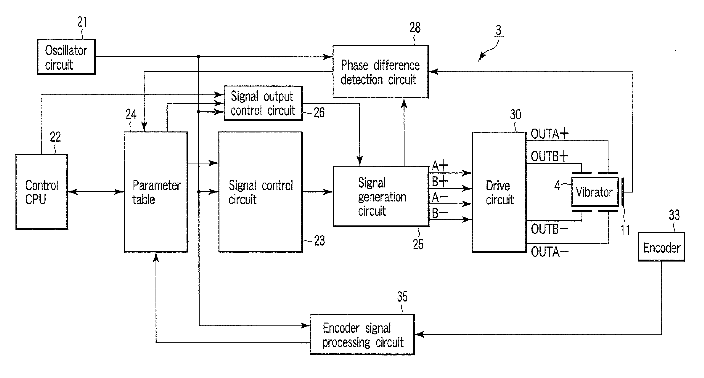
[0036]Initially, one example of an ultrasonic motor system to which a drive apparatus for an ultrasonic motor according to a first embodiment of the present invention is applied is described with reference to FIG. 1. FIG. 1 is a block diagram showing one schematic configuration example of an ultrasonic motor system.
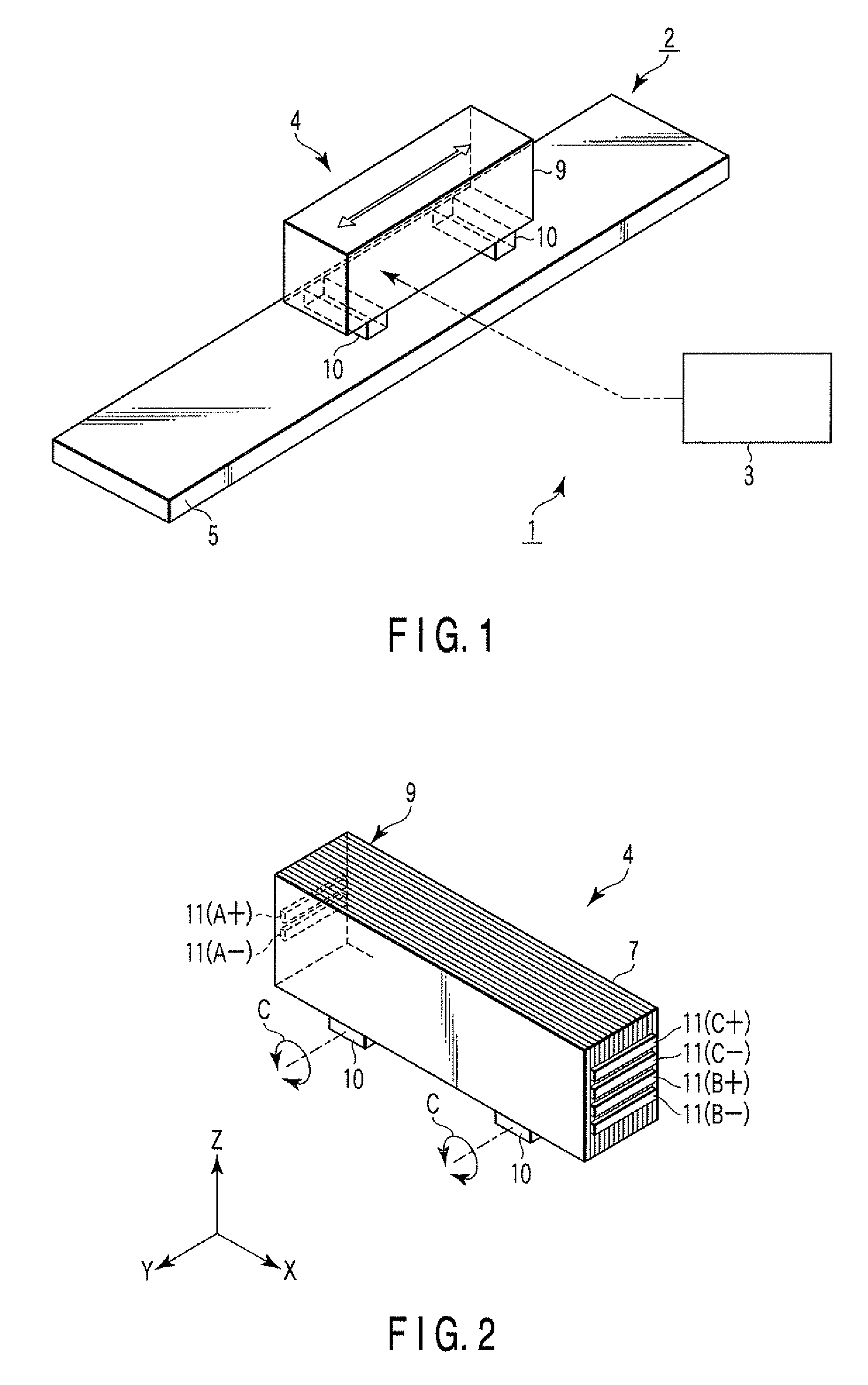
[0037]As shown in FIG. 1, an ultrasonic motor system 1 comprises an ultrasonic motor 2, and a drive apparatus 3 for driving the ultrasonic motor 2. The ultrasonic motor 2 has an ultrasonic vibrator 4, and a driven member 5 driven by the ultrasonic vibrator 4.
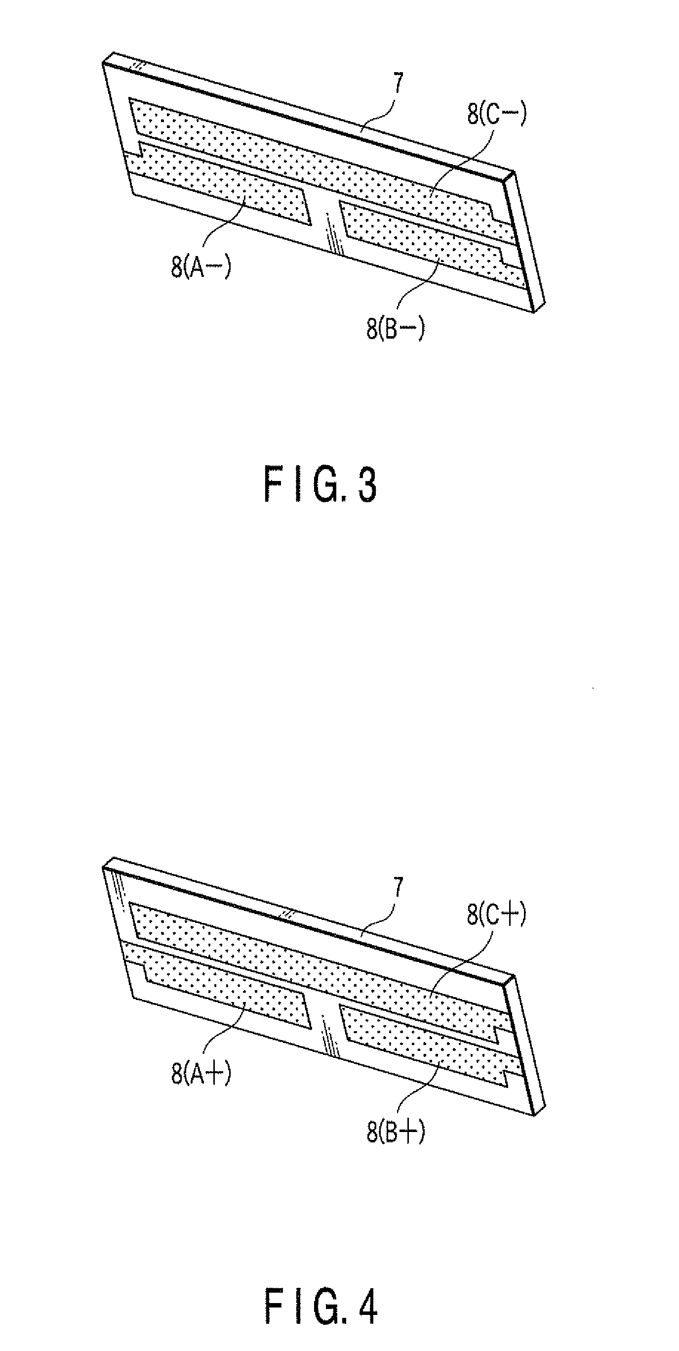
[0038]As shown in FIGS. 2 to 4, the ultrasonic vibrator 4 includes a rectangular parallelepiped piezoelectric stack 9 composed of a plurality of stacked sheet-shaped internal electrodes 8 provided on one side of rectangular plate-shaped piezoelectric ceramic sheets 7, and two frictional contacts 10 adhesively bonded to one surface of the piezoelectric stack 9.
[0039]As shown in FIGS. 3 and 4, each of the piezoelectric ...
second embodiment
[0100]A drive apparatus for an ultrasonic motor according to a second embodiment of the present invention is described below. It is to be noted that the difference between this drive apparatus for the ultrasonic motor and the drive apparatus for the ultrasonic motor according to the first embodiment described above is only explained.
[0101]In the above first embodiment, as described with reference to FIGS. 15 and 16, in stopping the driving of the ultrasonic motor 2, the output of the signal control circuit 23 is once stopped, and then the burst drive is performed by applying the single burst signal to the ultrasonic vibrator 4 with the predetermined timing. Thus, the generation of the residual vibration corresponding to the natural frequency of the vibration system of the ultrasonic motor 2 is inhibited.
[0102]On the other hand, in the present second embodiment, as shown in FIG. 17, in stopping the driving of the ultrasonic motor 2, the output of the signal control circuit 23 is once...
PUM
 Abstract
Description
Claims
Application Information
 - R&D
- Intellectual Property
- Life Sciences
- Materials
- Tech Scout
- Unparalleled Data Quality
- Higher Quality Content
- 60% Fewer Hallucinations
Browse by: Latest US Patents, China's latest patents, Technical Efficacy Thesaurus, Application Domain, Technology Topic, Popular Technical Reports.
© 2025 PatSnap. All rights reserved.Legal|Privacy policy|Modern Slavery Act Transparency Statement|Sitemap|About US| Contact US: help@patsnap.com


