Base station, receiving device, mobile terminal, and frequency sharing method

a technology of base station and receiving device, applied in the field of wireless communication systems, can solve the problems of difficult to improve frequency use efficiency, difficult to apply the first method to a communication system, and problems in the above-referenced technology

Inactive Publication Date: 2009-04-02
NTT DOCOMO INC
View PDF3 Cites 71 Cited by
  • Summary
  • Abstract
  • Description
  • Claims
  • Application Information

AI Technical Summary

Benefits of technology

[0010]Aspects of the present invention provide a base station, a receiving device, a mobile terminal, and a frequency sharing method that solve or reduce one or more problems caused by the limitations and disadvantages of the related art.

Problems solved by technology

However, the above related art technologies have problems as described below.
With the first method, because transmission power control is not performed flexibly according to operating conditions of other systems, it is difficult to improve frequency use efficiency.
Also, it is theoretically difficult to apply the first method to a communication system such as a cellular system where signals are transmitted in a wide area using comparatively high transmission power.
Also with the second method, because whether it is possible to transmit a signal is determined based only on surrounding conditions without taking into account transmission parameters, it is difficult to efficiently use frequency resources.

Method used


Image

  • Base station, receiving device, mobile terminal, and frequency sharing method
  • Base station, receiving device, mobile terminal, and frequency sharing method
  • Base station, receiving device, mobile terminal, and frequency sharing method

Examples


first embodiment

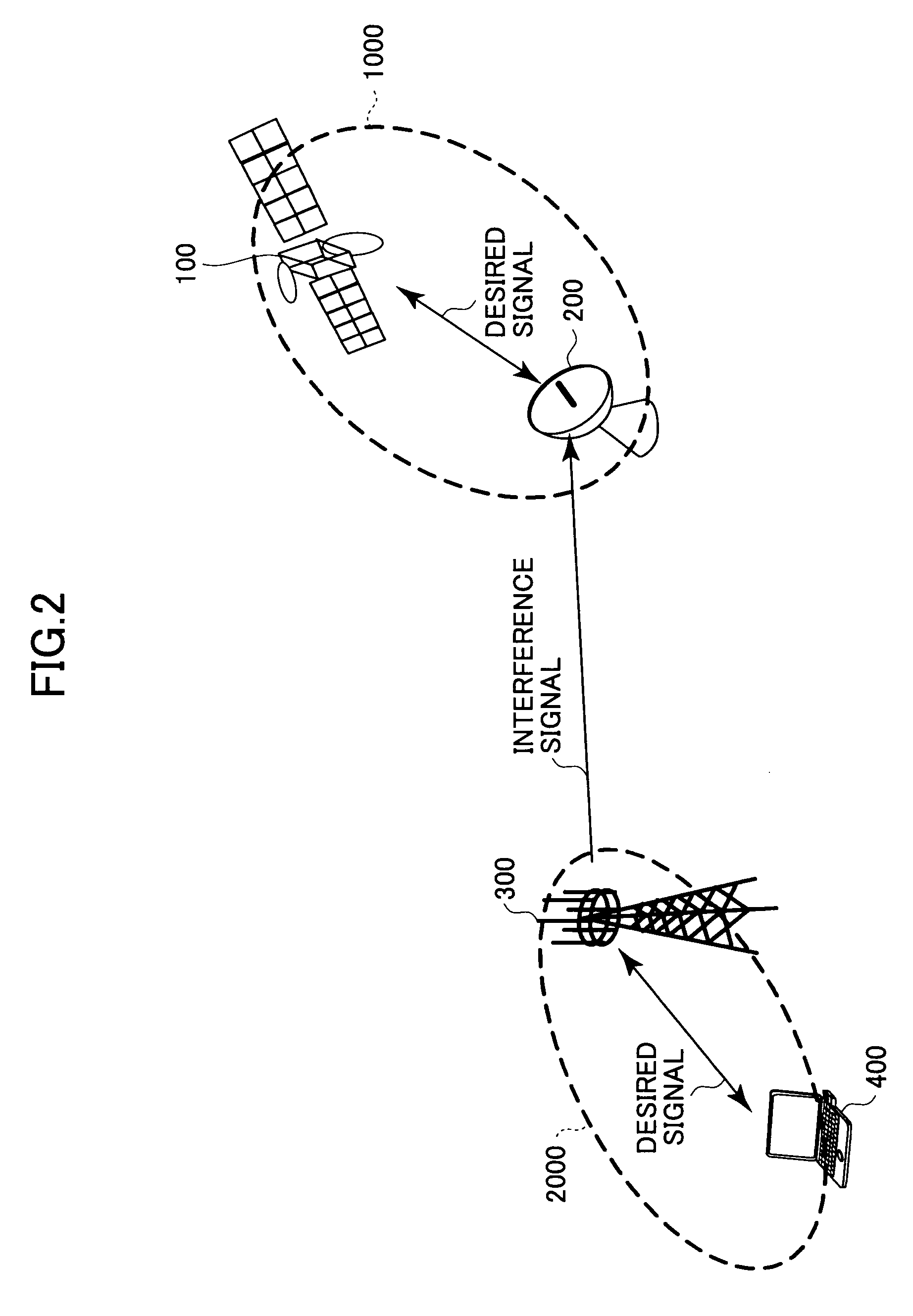
[0042]A wireless communication system according to a first embodiment of the present invention is described below with reference to FIG. 2.

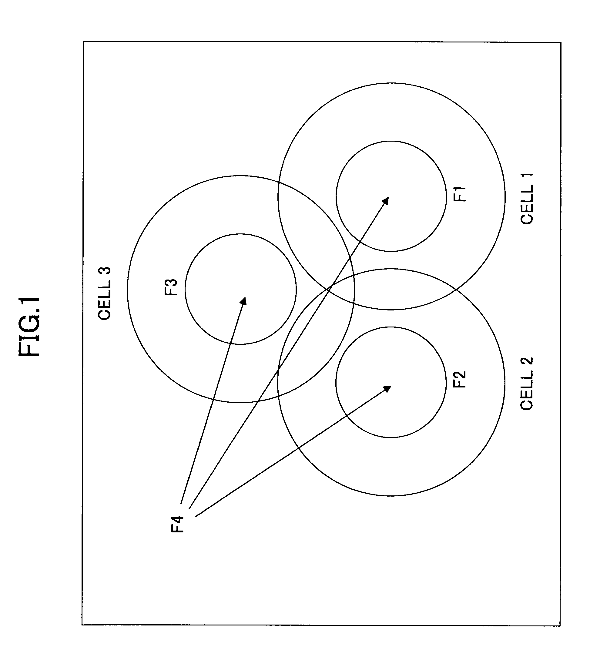
[0043]A wireless communication system 2000 of this embodiment is used in the same area as and / or an area close (adjacent) to that where a wireless communication system 1000 is used. Also, as shown in FIG. 3, the wireless communication system 2000 uses the same frequency band as and / or a frequency band close (adjacent) to that used by the wireless communication system 1000.

[0044]In this embodiment, the wireless communication system 1000 represents an existing wireless communication system and is given priority over the wireless communication system 2000. In the example shown in FIG. 2, the wireless communication system 1000 is represented by a satellite broadcasting system and the wireless communication system 2000 is represented by a mobile communication system.

[0045]The wireless communication system 1000 includes a transmitting device 100 and a ...

second embodiment

[0070]A wireless communication system according to a second embodiment of the present invention is described below.

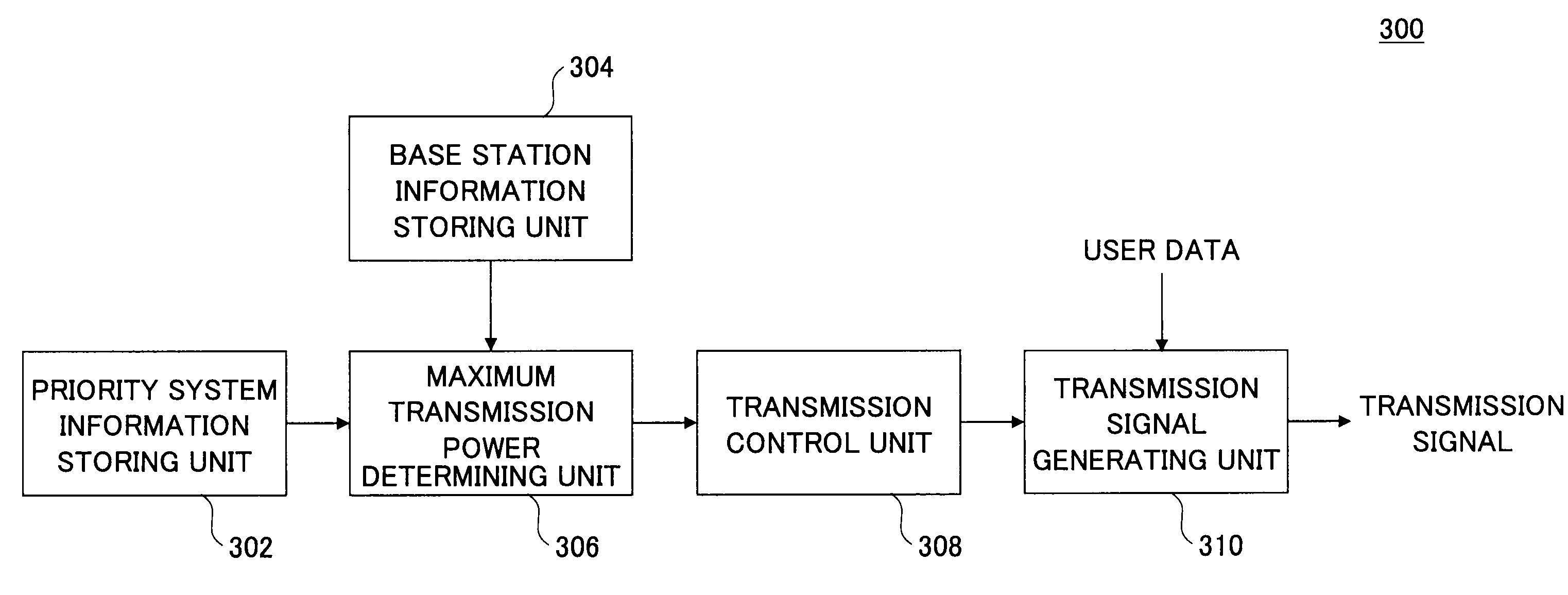
[0071]The configuration of the wireless communication system of this embodiment is substantially the same as that described with reference to FIG. 2. Also, the configuration of the base station 300 of this embodiment is substantially the same as that described with reference to FIG. 4.

[0072]In the first embodiment, the maximum transmission power is determined based on the distance between the receiving device 200 of the wireless communication system 1000 and the transmitting device of the base station 300 of the wireless communication system 2000. In practice, however, as shown in FIG. 7, the degree of influence exerted on the receiving device 200 of the wireless communication system 1000 by the transmitting device of the base station 300 of the wireless communication system 2000 varies greatly depending on, for example, the difference in height between the receiving de...

third embodiment

[0079]A wireless communication system according to a third embodiment of the present invention is described below.

[0080]The configuration of the wireless communication system of this embodiment is substantially the same as that described with reference to FIG. 2. Also, the configuration of the base station 300 of this embodiment is substantially the same as that described with reference to FIG. 4.

[0081]In the above embodiments, the maximum transmission power is determined based on the interference on the wireless communication system 1000 caused by a spurious signal.

[0082]However, there is a case where the influence of an out-of-band signal received by the receiving device 200 outside of the operating frequency band is greater than the influence of a spurious signal in the operating frequency band. Such influence by an out-of-band signal is called desensitization. The desensitization is a form of interference caused when a non-linear element of the receiving device 200 incorporates ...


PUM


Abstract

A disclosed base station is used in a first wireless communication system using a first frequency band that is the same as or adjacent to a second frequency band used by a second wireless communication system, and includes a propagation loss estimation unit configured to estimate propagation loss of a signal in the first frequency band when the signal arrives at a receiving device of the second wireless communication system; a frequency difference calculation unit configured to calculate a frequency difference between the first frequency band and the second frequency band; a maximum transmission power determining unit configured to determine maximum transmission power based on the estimated propagation loss and the calculated frequency difference; and a transmission control unit configured to transmit a signal with transmission power less than or equal to the maximum transmission power determined by the maximum transmission power determining unit.

Description

BACKGROUND OF THE INVENTION[0001]1. Field of the Invention[0002]The present invention generally relates to wireless communication systems. More particularly, the present invention relates to a base station, a receiving device, a mobile terminal, and a frequency sharing method.[0003]2. Description of the Related Art[0004]There is a known method (hereafter called a first method) for sharing the same frequency band by multiple systems in short-distance communications using, for example, ultra-wideband (UWB). In the first method, transmission power of a system is limited to a low level based on a transmission power mask determined statically according to relationships with other systems sharing the same frequency band.[0005]There is another known method (hereafter called a second method) used, for example, in wireless LANs. In the second method, a terminal determines whether an allocated frequency band is being used by a neighboring terminal before starting communications and refrains f...

Claims


Application Information

Patent Timeline
Patent Type & Authority Applications(United States)
IPC IPC(8): H04B7/00
CPCH04W16/14H04W52/242Y02B60/50H04W88/08H04W52/367
Inventor FUJII, HIROMASAYOSHINO, HITOSHI
Owner NTT DOCOMO INC
Why Eureka
Try Eureka