Co-fired ceramic module

a ceramic module and ceramic technology, applied in the field of ceramic modules, can solve the problems of heat dissipation problem, circuit board has to be punched, original structure of the circuit board damaged, etc., and achieve the effects of high thermal conductivity, high thermoconductive efficiency, and high thermal conductivity

Inactive Publication Date: 2009-04-09
DELTA ELECTRONICS INC
View PDF1 Cites 19 Cited by
  • Summary
  • Abstract
  • Description
  • Claims
  • Application Information

AI Technical Summary

Benefits of technology

[0011]As mentioned above, the high thermal conductivity material is added to the co-fired ceramic module of the invention and then co-fired with the co-fired ceramic module to form the ceramic substrate. Thus, the high thermoconductive efficiency can be provided to the heat-emitting devi...

Problems solved by technology

However, the reduction of the size brings the heat dissipating problem.
However, the circuit board has to be punched and the original structure thereof is damaged.
Consequent...

Method used


Image

  • Co-fired ceramic module
  • Co-fired ceramic module
  • Co-fired ceramic module

Examples


first embodiment

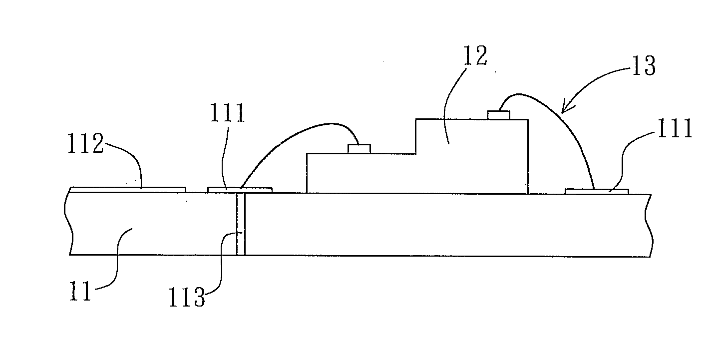
[0024]Referring to FIG. 1, a co-fired ceramic module 1 according to a first embodiment of the present invention includes a ceramic substrate 11 and at least one heat-emitting device 12. The ceramic substrate 11 has at least one high thermal conductivity material. The high thermal conductivity material has a high coefficient of heat conductivity, and is, for example but not limited to, aluminum nitride, silicon carbide, sapphire or beryllium oxide (BeO). The heat-emitting device 12 is disposed on the ceramic substrate 11. Herein, the heat-emitting device 12 is disposed on a surface of the ceramic substrate 11.

[0025]The ceramic substrate 11 is a low-temperature co-fired ceramics (LTCC) substrate and can be a multi-layer or single-layer plate. The method of preparing the ceramic substrate 11 will be described with reference to the single-layer plate. First, a ceramic material, an inorganic adhesive, the high thermal conductivity material and other necessary materials are mixed to form ...

second embodiment

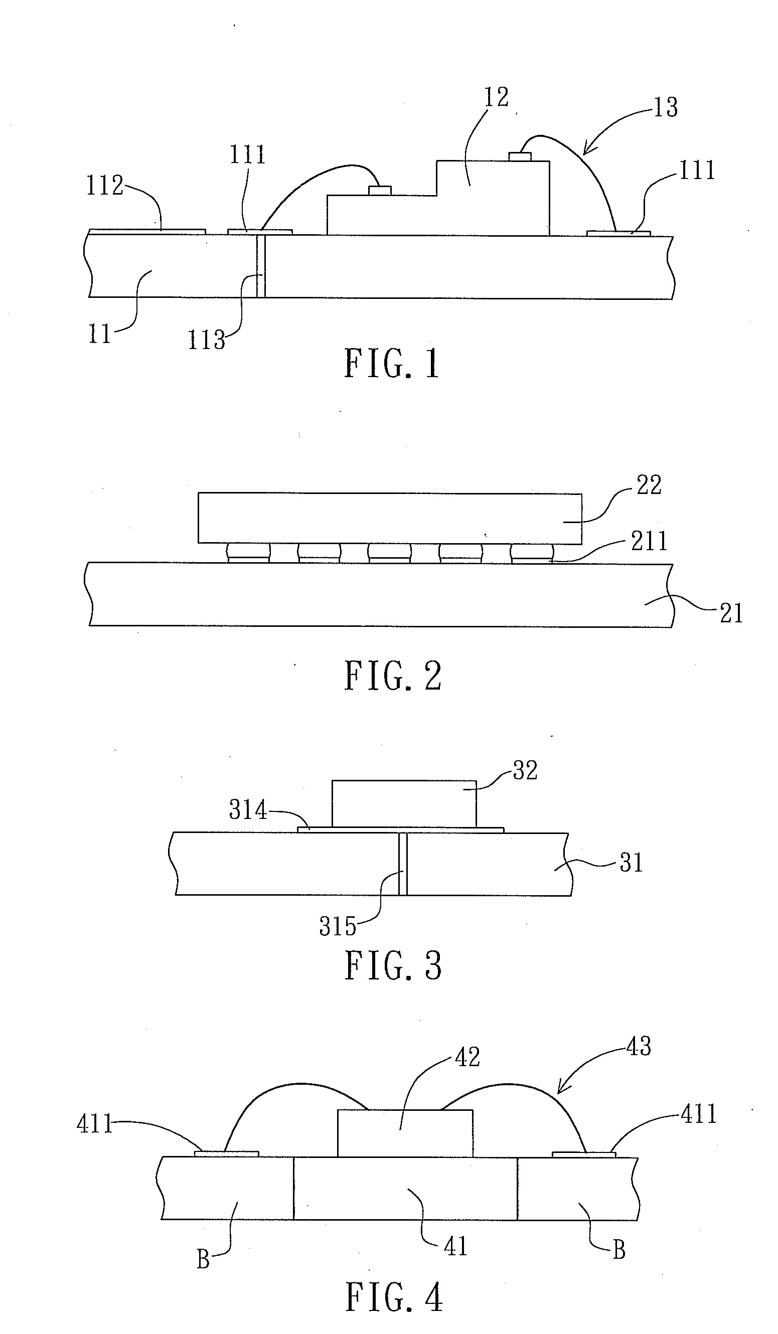
[0030]Referring to FIG. 2, a co-fired ceramic module 2 according to a second embodiment of the present invention includes a ceramic substrate 21 and at least one heat-emitting device 22. The second embodiment is different from the first embodiment mainly in that the ceramic substrate 21 is a circuit board, and the heat-emitting device 22 is a package body. Herein, the heat-emitting device 22 is directly disposed on connection pads 211 of the ceramic substrate 21 by way of the ball grid array (BGA) package. In addition, the heat-emitting device 22 can also be disposed on the ceramic substrate 21 in other manners, such as the quad flat package (QFP), the surface mount technology (SMT) or the pin grid array (PGA) package.

third embodiment

[0031]Referring to FIG. 3, a co-fired ceramic module 3 according to a third embodiment of the present invention includes a ceramic substrate 31 and at least one heat-emitting device 32 disposed on the ceramic substrate 31. The ceramic substrate 31 has a metal layer 314 and a thermal via hole 315. The metal layer 314 is connected to the heat-emitting device 32. The metal layer 314 and the thermal via hole 315 can increase the thermoconductive efficiency of the ceramic substrate 31.


PUM


Abstract

A co-fired ceramic module includes a ceramic substrate and at least one heat-emitting device. The ceramic substrate has at least one high thermal conductivity material. The heat-emitting device is disposed on the ceramic substrate. The substrate further includes a cavity and the heat-emitting device is disposed in the cavity.

Description

CROSS REFERENCE TO RELATED APPLICATIONS[0001]This Non-provisional application claims priority under 35 U.S. §119(a) on Patent Application No(s). 096137365 filed in Taiwan, Republic of China on Oct. 5, 2007, the entire contents of which are hereby incorporated by reference.BACKGROUND OF THE INVENTION[0002]1. Field of Invention[0003]The invention relates to a ceramic module and, in particular, to a co-fired ceramic module.[0004]2. Related Art[0005]Recently, portable information electronic products and mobile communication products are developed toward the miniaturized, multi-functional, highly reliable and low priced trends, so the high-element density has become the developing trend of the electronic product. Therefore, active devices and passive devices used in the circuit have been developed toward the integrated, modularized and on-chip directions so that the size of the circuit can be effectively reduced, the cost can be lowered and the competition ability of the product can be e...

Claims


Application Information

Patent Timeline
IPC IPC(8): H01L23/373
CPCH01L21/4807H01L23/15H01L2924/01327H01L23/3677H01L2924/09701H05K1/0203H05K1/0206H05K1/0306H05K3/4611H05K3/4629H05K2201/0187H05K2201/0209H05K2201/10106H01L2224/16225H01L2224/49107H01L2924/00
Inventor WEI, CHIH-HUNGHSIEH, YU-PING
Owner DELTA ELECTRONICS INC
Why Eureka
Try Eureka