Chip card receiving device comprising a carriage for holding a chip card

a chip card and receiving device technology, applied in the direction of maintaining the alignment of the head carrier, manufacturing tools, instruments, etc., can solve the problems of increased risk of contact interruption between the read/write contact assembly, chip cards are not always handled with the requisite care, chip cards can be damaged or deformed, etc., and achieve the effect of saving spa

Inactive Publication Date: 2009-04-09
SIEMENS AG
View PDF5 Cites 7 Cited by
  • Summary
  • Abstract
  • Description
  • Claims
  • Application Information

AI Technical Summary

Benefits of technology

[0007]The task underlying the invention was therefore to create a chip card receiving device suitable for series production and for use in commercial vehicles which ensures absolutely secure transport of the chip cards and reliable contacting of the chip cards in the read / write position even if the chip cards are deformed or damaged and which can be realized with as much space-saving effect as possible.
[0011]The invention in particular offers the advantage that a high compressive load per unit area can be exerted so that even if the coefficient of friction is reduced by dirt contamination, adequately high holding forces are effective. Furthermore, as a result of the tongs function, i.e. the gripping of the clamping elements on both sides over a large area, and through the use of suitable frictional coverings a high adhesion effect is achieved between a chip card and the clamping elements, which ensures that a chip card is moved without slipping during transport and a chip card is held in the read / write position without being exposed to vibration and jolts, and because the carriage can be mounted on the carrier to a relatively tight tolerance, vibration-related abrasion of the chip card contacts is avoided. It can also be highlighted that a clamping element gripping around the contact field of an inserted chip card is effective as a holddown device in the direct contact area and in this way reliable contacting including of uneven chip cards is made possible. Moreover, despite its robust design the solution found offers a high level of security against manipulation as the clamping elements rest with considerable force on the entire width of a chip card and are also guided in grooves along the side, which means that they cannot be lifted up in the read / write position. As a result of the found solution it is therefore not essential to attach additional locking elements to the chip card receiving device, even if unlike in the preferred exemplary embodiment which provides for positively engaged transport of the carriage holding the chip cards independently of the care taken by the user, the chip cards are exclusively inserted by hand in the read / write position and are moved in a friction grip into the removal position by means of a suitably driven pushrod.
[0012]For the sake of completeness it should also be mentioned that although the application of the chip card receiving device in accordance with the solution is optimized for use in commercial vehicles, it is also eminently suitable for general use because it is relatively inexpensive to produce and install and including the drive system is low in height. In this context the preferred exemplary embodiment represents a useful, largely autonomous assembly which with the incorporation of suitable spacer bolts can be assigned to a printed circuit board with minimal space requirement. In addition, the design of the chip card receiving device with a torsionally rigid carrier, which for example can be configured as an outsert plate, and the direct assignment of the individual components and assemblies to the carrier, represents a minimal tolerance addition, so that the units can be produced with tolerances suitable for large series. Furthermore, it should be pointed out that a simplified version can be made by providing just one clamping element which works directly together with a suitably configured carriage on the side of the carriage facing the stationary contact assembly.

Problems solved by technology

Also, when chip cards are used in commercial vehicles an increased risk exists of contact interruptions between a read / write contact assembly and the chip cards because of the general environment in which they have to operate.
Furthermore, when chip cards are used in tachographs they have to be inserted and removed relatively frequently owing to changes of driver and vehicle as well as road traffic checks and the chip cards are not always handled with the requisite care.
As a result, and also because the chip cards are carried and kept outside the vehicle, the chip cards can be damaged or deformed.
Such deformations of chip cards as well as the unavoidable effects of operational vibrations and jolts must not, however, lead to the read / write contacts being damaged when the chip card is inserted in the receiving device or the function of the chip card being disrupted when it is in the read / write position.
The transport of the chip cards within the receiving device between the insertion / removal position and the read / write position represents a further problem.
If a chip card is inserted exclusively by hand there is a risk that it will not be exactly positioned in the read / write position.
The operational environment in the commercial vehicle and the dirt, in particular from oils and greases, encountered owing to the relatively frequent handling of the chip cards, as well as the tolerances and thickness differences of the chip cards from large production series mean, however, that an apparently appropriate transport arrangement with a suitably driven friction shaft or with friction rollers does not offer adequate transport reliability.
This is because if the chip card jammed, especially during transport to the removal position, the functioning of the tachograph concerned would be considerably disrupted.
It does not, however, offer a holddown function for curved or bent chip cards.
Moreover, the gripping function can be restricted or no longer apply at all in the case of deformed chip cards.
A further disadvantage exists in that the gripping function can be simply manipulated by reducing the width of a chip card.

Method used


Image

  • Chip card receiving device comprising a carriage for holding a chip card
  • Chip card receiving device comprising a carriage for holding a chip card
  • Chip card receiving device comprising a carriage for holding a chip card

Examples


Embodiment Construction

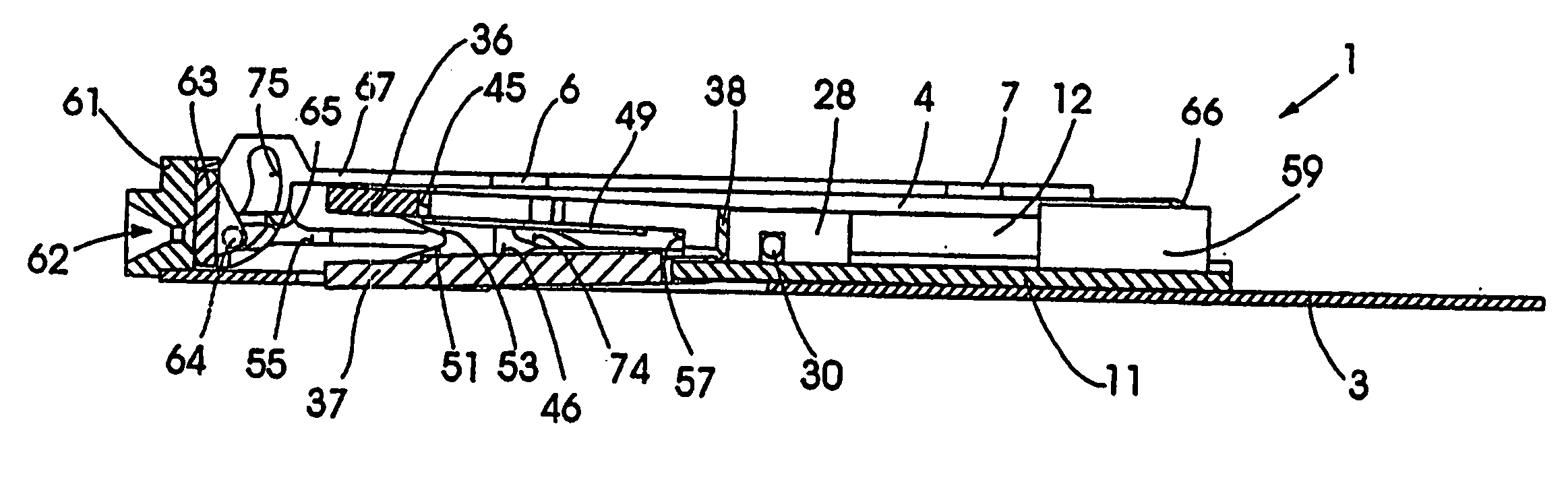
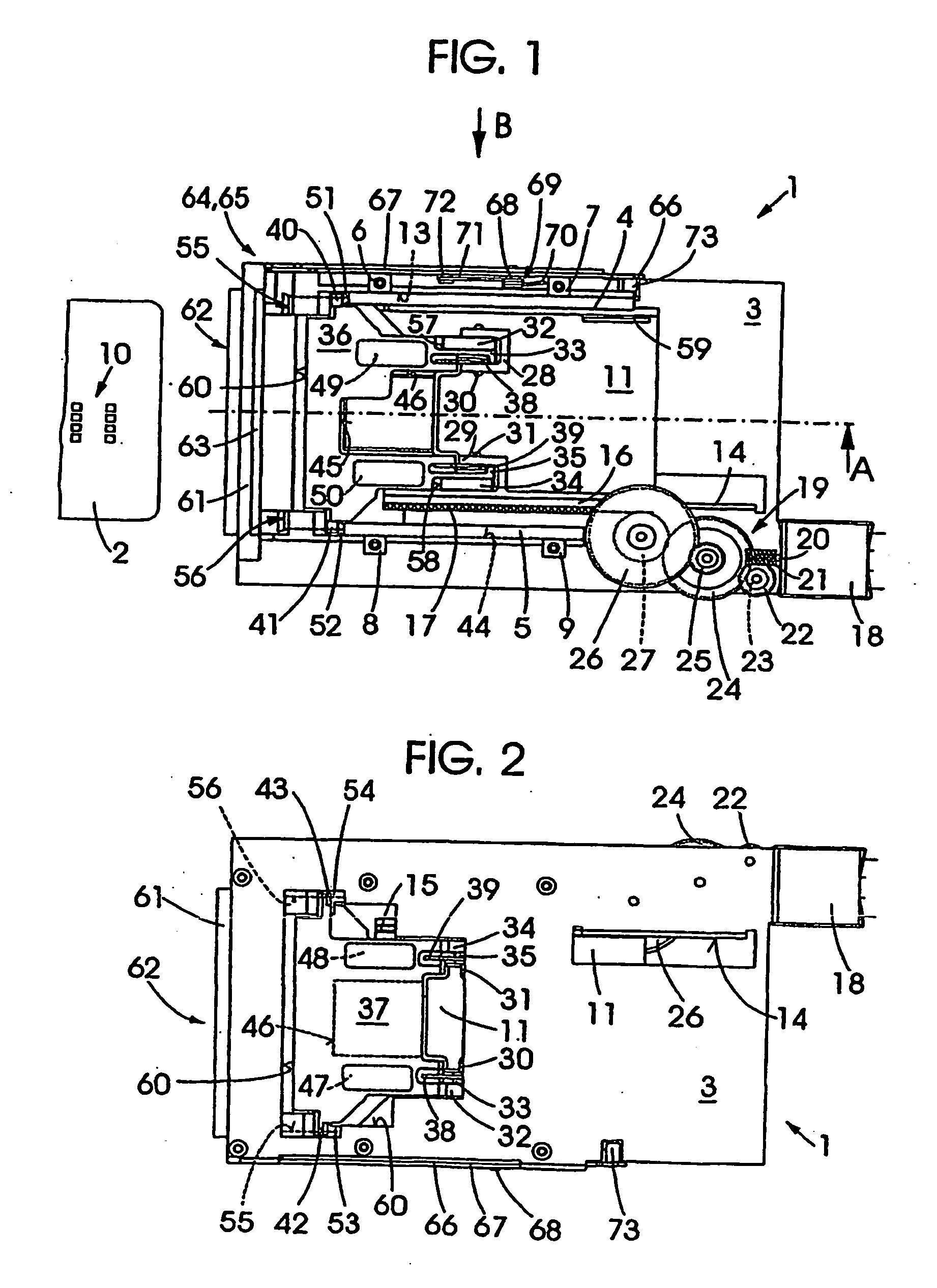
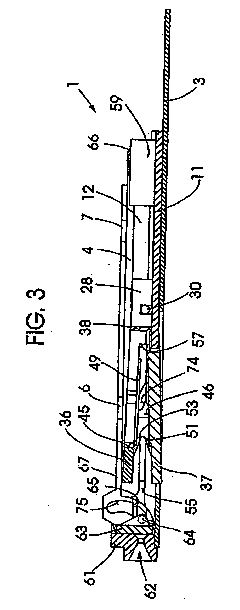
[0019]As can be seen from the drawings, the chip card receiving device 1, to which a chip card 2 has been symbolically assigned, exhibits a torsionally rigid carrier 3 on which rails 4 and 5 are fastened, preferably formed on by outsert injection molding. The supports 6, 7, 8 and 9 assigned to the rails 4, 5 and featuring tapped holes not further designated serve the purpose of fastening the chip card receiving device 1, e.g. onto a printed circuit board on which expediently a contact assembly assigned to the board contacts 10 of the chip cards 2 is arranged. With 11 a carriage is designated which by means of a cheek 12 engages with an undercut 13 provided in the rail 4 and which is mounted moveably in longitudinal direction on a strip 14 configured on the carrier 3, to which strip a slot 15 (FIG. 2) configured in the carriage 11 is assigned. A further cheek 16 of the carriage 11 features toothing 17 via which the carriage 11 is functionally connected by means of gearing with a posi...


PUM


Abstract

A chip-card-receiving device has a carriage for holding a chip card, means for fixing and releasing a chip card, and a clamping element. The carriage is displaceably mounted between an insertion / removal position and a reading / writing position on a carrier. The clamping element is spring-mounted on the carriage such that the clamping element rests resiliently on an inserted chip card. The clamping element has ramps formed on the carrier such that the clamping element is lifted from a plane of the chip card in an insertion / removal position of the carriage.

Description

CROSS REFERENCE TO RELATED APPLICATIONS[0001]The present application is a continuation of International Application PCT / DE03 / 00442, filed Feb. 13, 2003, which designated the United States, and further claims priority to German Patent Application 10208259.6, filed Feb. 26, 2002, the both of which are herein incorporated by reference.BACKGROUND OF THE INVENTION[0002]The invention relates to a chip card receiving device comprising a carriage for holding a chip card which is moveably mounted on a carrier between an insertion / removal position and a read / write position, and also comprising means for tightly clamping and releasing a chip card.[0003]The use of chip cards, for example to record the personal working and resting times of the drivers of commercial vehicles, requires reliable safeguards to prevent disruptions, caused for purposes of deception, to the data transfer between the data recording device, in this case a tachograph, and a chip card, owing to the documentary value of the...

Claims


Application Information

Patent Timeline
Patent Type & Authority Applications(United States)
IPC IPC(8): B25J15/06G06K7/00G06K17/00G06K13/08
CPCG06K7/0021G06K13/085G06K13/08
Inventor HAUTVAST, HEINZ-JOSEFRIESTER, THOMAS
Owner SIEMENS AG
Why Eureka
Try Eureka