Temperature-sensor circuit, and temperature compensated piezoelectric oscillator

a piezoelectric oscillator and temperature-compensated technology, applied in the field of temperature-sensor circuits and temperature-compensated piezoelectric oscillators, can solve the problems of unsatisfactory temperature sensor output, unfavorable linearity of output voltage with respect to temperature, and noise generating amplifiers affecting the output of temperature-compensated piezoelectric oscillators, etc., to achieve less noise, reduce voltage, and reduce the effect of nois

Active Publication Date: 2009-04-09
SEIKO EPSON CORP
View PDF14 Cites 10 Cited by
  • Summary
  • Abstract
  • Description
  • Claims
  • Application Information

AI Technical Summary

Benefits of technology

[0008]An advantage of the invention is to provide a temperature-sensor circuit enabling voltage reduction while having less noise, and a temperature compensated piezoelectric oscillator using the same.
[0009]A temperature-sensor circuit according to a first aspect of the invention includes: a transistor having an emitter that is grounded, a collector, and a base; a first resistor having a first end and a second end, the first end being coupled with the collector; and a second resistor having a third end and a fourth end, the third end being coupled with the second end of the first resistor. A junction joining the first resistor and the second resistor is coupled with the base.
[0010]This configuration has an advantage to provide a temperature-sensor circuit enabling voltage reduction while having less noise resulting from using a transistor as a diode.
[0011]A temperature-sensor circuit according to a second aspect of the invention includes: a first transistor having a first emitter that is grounded, a first collector, and a first base; a first resistor having a first end and a second end, the first end being coupled with the first collector; a second resistor having a third end and a fourth end, the third end being coupled with the second end of the first resistor; a second transistor having a second emitter that is coupled with the first collector, a second collector, and a second base; a third resistor having a fifth end and a sixth end, the fifth end being coupled with the second collector; a fourth resistor having a seventh end and an eighth end, the seventh end being coupled with the sixth end of the third resistor. A junction of the first resistor and the second resistor is coupled with the first base, while a junction of the third resistor and the fourth resistor is coupled with the second base, and the fourth end of the second resistor is coupled with the eighth end of the fourth resistor.
[0012]This can lead an effect to provide a temperature-sensor circuit that can reduce a voltage and have less noise while having high temperature sensitivity of an output voltage.
[0013]Further, in the temperature-sensor circuits as above, a variable supply that increases a voltage level as a temperature rises may be employed as a power supply. This has an advantage to improve temperature sensitivity as variation of the output voltage with respect to the temperature becomes large, in addition to a low voltage and less noise.

Problems solved by technology

Therefore, the temperature sensor is not suitable for satisfying a recent requirement for a low voltage.
Further, the temperature sensor using the thermistor TH as a temperature-sensitive element as shown in FIG. 9C has a problem in that linearity of the output voltage with respect to the temperature is unfavorable.
Further, as shown in FIG. 9D, the temperature sensor using one diode as a temperature-sensitive element and amplifying an output voltage with an amplifier has a problem in that a noise generating from the amplifier affects an output of a temperature compensated piezoelectric oscillator.

Method used


Image

  • Temperature-sensor circuit, and temperature compensated piezoelectric oscillator
  • Temperature-sensor circuit, and temperature compensated piezoelectric oscillator
  • Temperature-sensor circuit, and temperature compensated piezoelectric oscillator

Examples


first embodiment

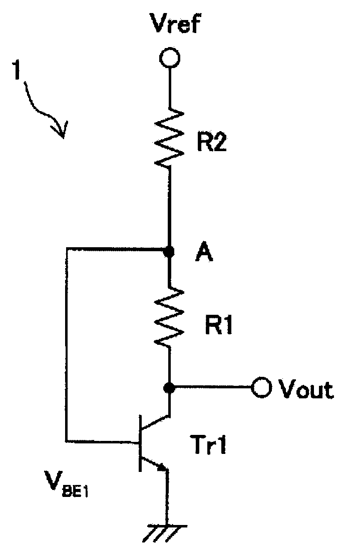
[0036]FIG. 1A is a circuit diagram showing a configuration of a temperature sensor according to the invention.

[0037]A temperature-sensor circuit 1 shown in FIG. 1A includes a transistor Tr1 and a series circuit in which a resistor R1 serving as a first resistor and a resistor R2 serving as a second resistor are coupled in series. An end of the resistor R1 in the series circuit is coupled with a collector of the transistor Tr1 while an end of the resistor R2 in the series circuit is coupled with a reference supply (reference voltage Vref). Further, a base of the transistor Tr1 is coupled with a junction joining the resistor R1 and the resistor R2 while an emitter of the transistor Tr1 is grounded.

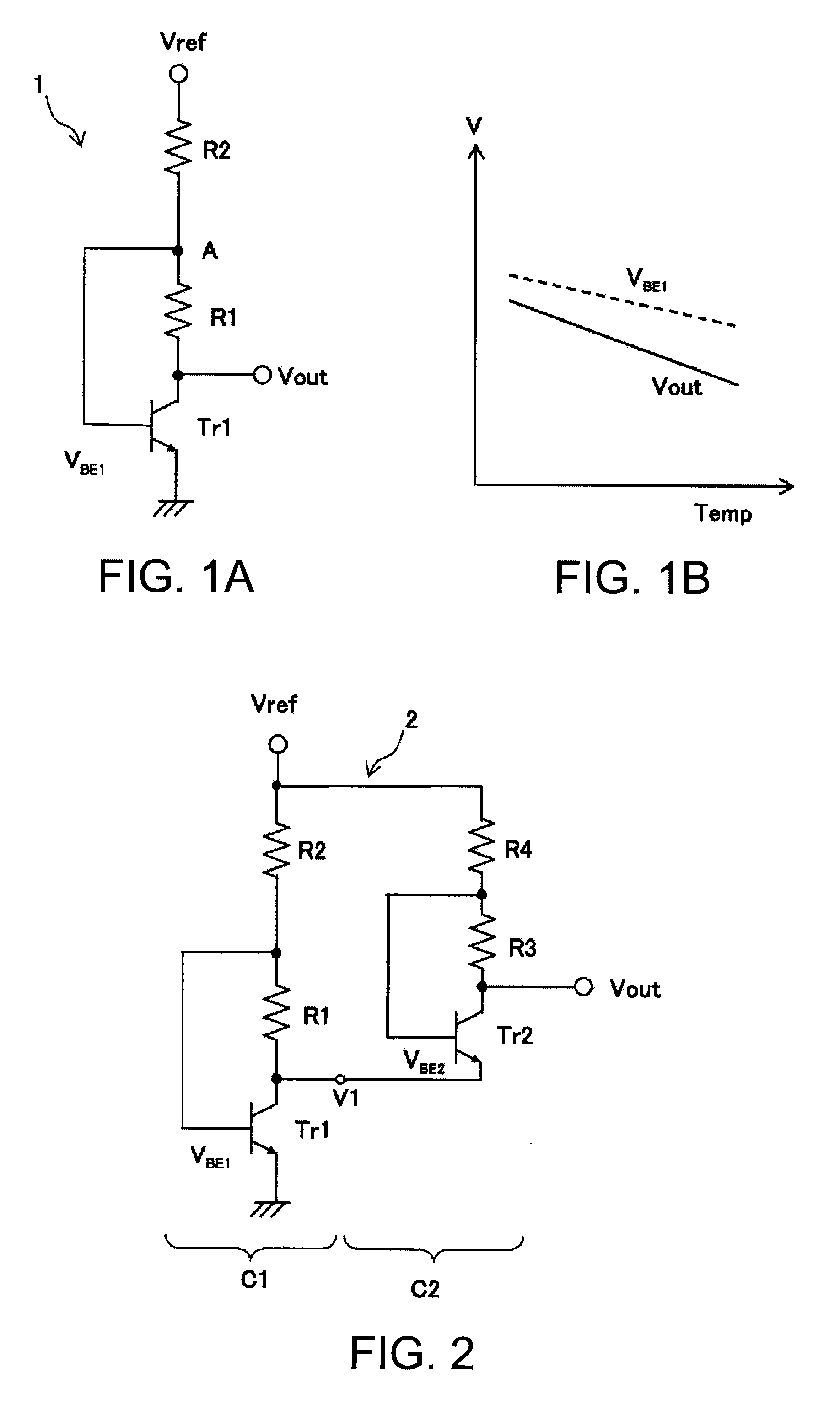
[0038]In FIG. 1B, a temperature characteristic of a base-emitter voltage VBE1 of the transistor Tr1 in the temperature-sensor circuit 1 shown in FIG. 1A is indicated in a dashed line, while an output voltage Vout is indicated in a full line. The output voltage Vout has a characteristic to de...

second embodiment

[0039]FIG. 2 is a circuit diagram showing a configuration of a temperature-sensor circuit according to a

[0040]A temperature-sensor circuit 2 includes a temperature sensor portion C1 and a temperature sensor portion C2. The temperature sensor portion C1 is configured similarly to the temperature-sensor circuit 1 shown in FIG. 1A. The temperature sensor portion C2 includes a transistor Tr2, and a series circuit including two resistors that are resistors R3 and R4. An end of the resistor R3 is coupled with a collector of the transistor Tr2, and the other end of the resistor R3 is coupled with a base, while an end of the resistor R4 is coupled with the other end of the resistor R3, and the other end of the resistor R4 is coupled with a reference supply (reference voltage Vref). Further, an output of the temperature sensor portion C1 is coupled with an emitter of the transistor Tr2 of the temperature sensor portion C2, so that an output is taken from the collector of the transistor Tr2.

[...

third embodiment

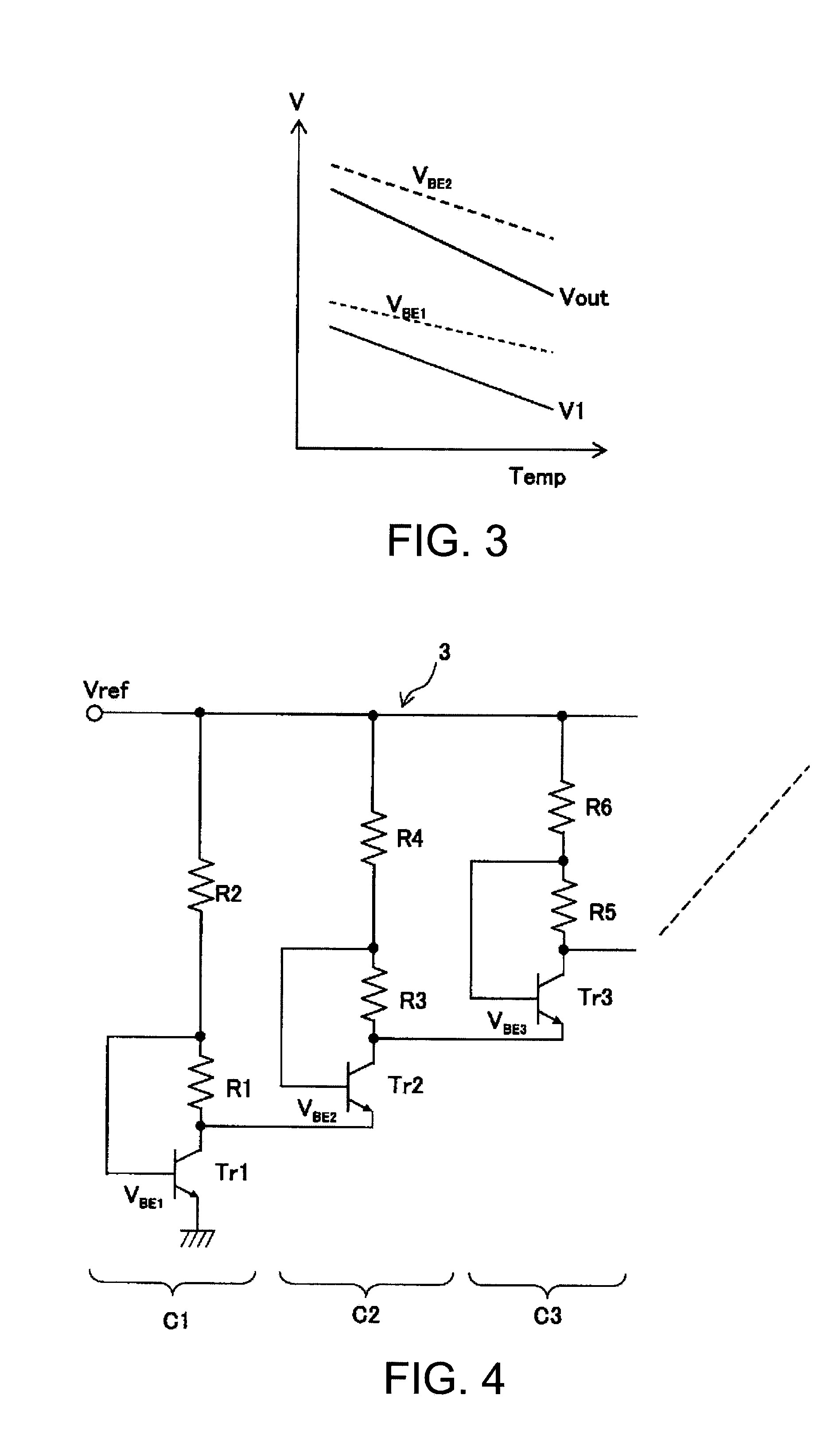
[0046]FIG. 4 is a circuit diagram showing a configuration of a temperature-sensor circuit according to a

[0047]A temperature-sensor circuit 3 shown in FIG. 4 includes a plurality of temperature sensor portions C1, C2, C3, . . . , that are coupled in a cascade.

[0048]In the third embodiment, the output (collector) of the temperature sensor portion C1 is coupled with the emitter in the temperature sensor portion C2 serving as a second temperature sensor portion, and further, the collector in the temperature sensor portion C2 is coupled with an emitter in the temperature sensor portion C3 serving as a third temperature sensor portion. Similarly, a collector of a transistor in a (i−1) th temperature sensor portion Ci−1(not illustrated) is sequentially coupled with an emitter of a transistor in a i-th temperature sensor portion Ci (not illustrated). Then, an output is taken from a collector of a transistor Trn (not illustrated) in a temperature sensor portion Cn (not illustrated) in a fina...


PUM


Abstract

A temperature-sensor circuit includes: a transistor having an emitter that is grounded, a collector, and a base; a first resistor having a first end and a second end, the first end being coupled with the collector; and a second resistor having a third end and a fourth end, the third end being coupled with the second end of the first resistor. A junction joining the first resistor and the second resistor is coupled with the base.

Description

BACKGROUND[0001]1. Technical Field[0002]The present invention relates to a temperature-sensor circuit that can operate with a particularly low voltage and is superior in voltage sensitivity with respect to a temperature, and a temperature compensated piezoelectric oscillator using the same.[0003]2. Related Art[0004]In recent years, a piezoelectric oscillator is used in many fields from communication device such as cellular phones to commercial-off-the-shelf devices such as a quartz-crystal clock due to its high frequency stability, compact size and lightweight, low cost, and the like. In particular, a temperature compensated piezoelectric oscillator (TCXO) compensating a frequency temperature characteristic of a piezoelectric resonator is widely used in cellular phones and the like that require frequency stability.[0005]JP-A-6-276020 discloses a temperature compensated crystal oscillator provided with a voltage generating circuit generating a desired voltage based on a temperature s...

Claims


Application Information

Patent Timeline
Patent Type & Authority Applications(United States)
IPC IPC(8): H01L35/00
CPCH03L1/022G01K7/01
Inventor KIYOHARA, ATSUSHI
Owner SEIKO EPSON CORP
Why Eureka
Try Eureka