Optical coherence tomographic apparatus

a tomographic apparatus and optical coherence technology, applied in the field of optical coherence tomographic apparatus, can solve the problems of disturbance of the image in the retina tomogram, interference between the light reflecting from the reference mirror and the interference of the light reflecting from the sample,

Inactive Publication Date: 2009-04-09
CANON KK
View PDF6 Cites 38 Cited by
  • Summary
  • Abstract
  • Description
  • Claims
  • Application Information

AI Technical Summary

Problems solved by technology

The light reflected by the reference mirror and the light reflected by the sample are caused to interfere with each other.
This may cause a disturbance of the image in the retina tomogram, called “motion artifact”.

Method used


Image

  • Optical coherence tomographic apparatus
  • Optical coherence tomographic apparatus
  • Optical coherence tomographic apparatus

Examples


first working example

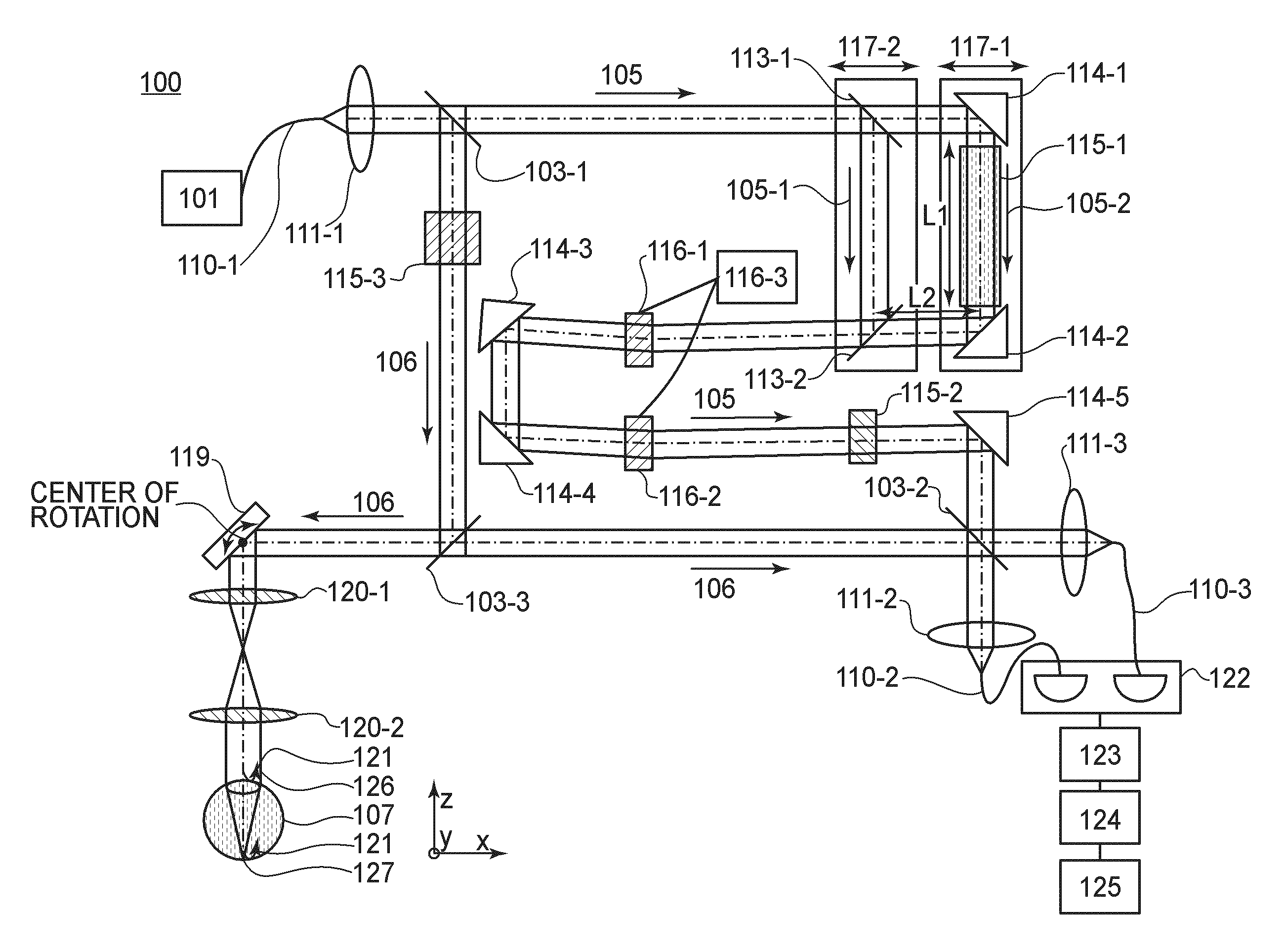
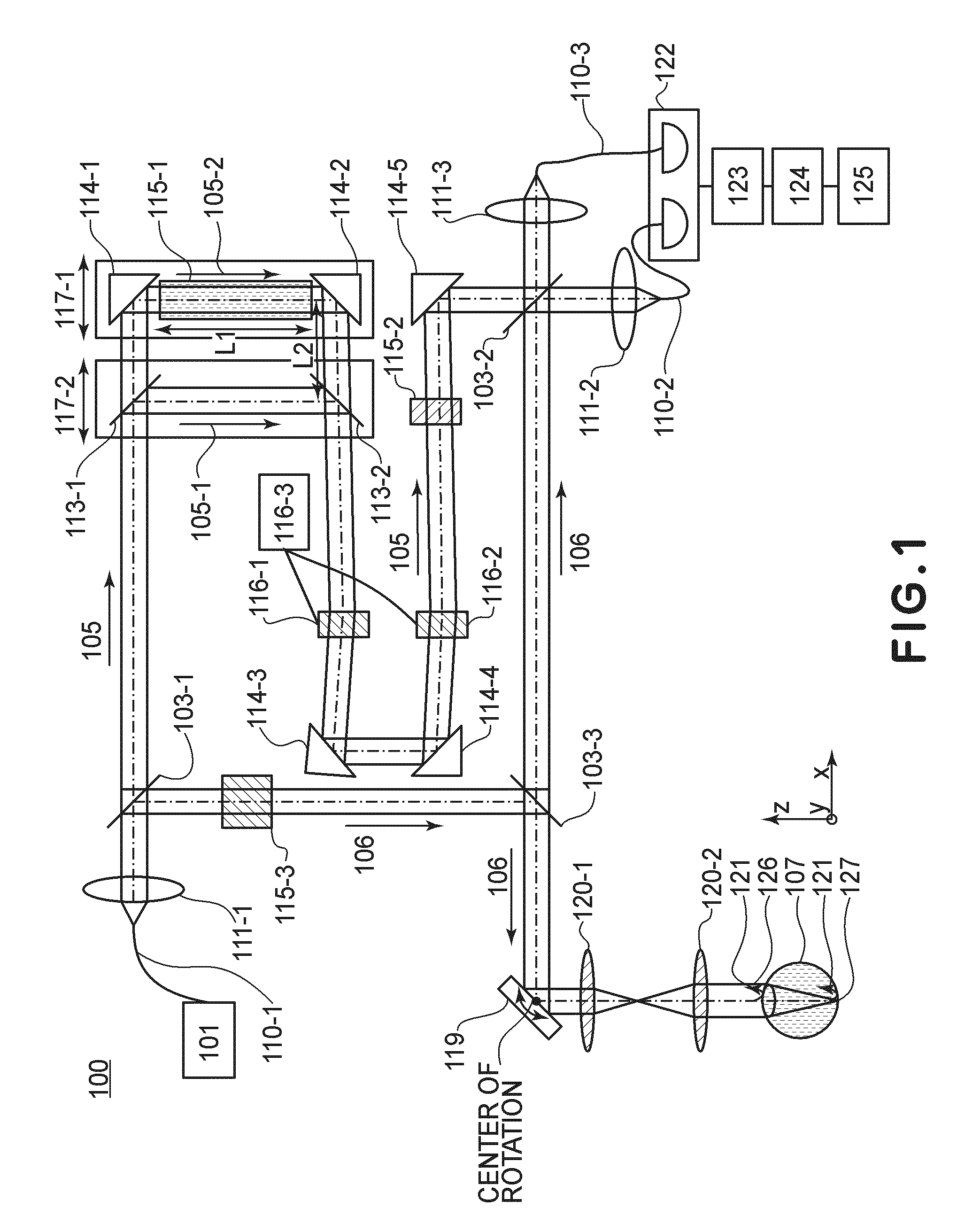
[0061]Referring to FIG. 1, an OCT apparatus according to the first working example will be explained.

[0062]FIG. 1 is a schematic diagram for explaining an optical system in the OCT apparatus of this working example.

[0063]Denoted in FIG. 1 at 100 is an OCT apparatus, and denoted at 103 and 113 are beam splitters. Denoted at 105 is a reference light, and denoted at 106 is a measuring light. Denoted at 107 is an eye to be examined, and denoted at 110 is a single mode fiber. Denoted at 111 and 120 are lenses, and denoted at 114 is a mirror.

[0064]Denoted at 115 is a dispersion compensation glass, and denoted at 119 is an XY scanner. Denoted at 122 is a balanced detector, and denoted at 123 is an amplifier. Denoted at 124 is a filter, and denoted at 125 is a personal computer (PC). Denoted at 126 a cornea of the eye to be examined, and denoted at 127 is a retina of the eye to be examined.

[0065]In this working example, the OCT apparatus 100 is used as a device for acquiring a tomogram of t...

second working example

[0121]The second working example will be described with reference to a structural example wherein the light path of at least one of the inspection optical system, detection optical system and reference optical system described hereinbefore is comprised of an optical fiber.

[0122]FIG. 4 is a schematic diagram for explaining the structure of the OCT apparatus in the second working example of the present invention.

[0123]In FIG. 4, like numerals are assigned to components similar or corresponding to those of the first working example illustrated in FIG. 1. Thus, description of the duplicated structure will be omitted.

[0124]In FIG. 4, denoted at 200 is an OCT apparatus, and denoted at 130 is a single mode fiber. Denoted at 131 is an optical coupler, and denoted at 134 is an optical circulator.

[0125]In this working example, the OCT apparatus 200 is used as a device for acquiring a tomogram of the retina 127 of an eye 107 to be examined. Furthermore, in this working example, by constituting...


PUM


Abstract

An optical coherence tomographic apparatus wherein a reference light path includes at least a first reference light path and a second reference light path having an optical path length shorter than that of the first reference light path, wherein first tomographic information of the object at a first inspection position based on the optical interference using the first reference light path and second tomographic information of the object at a second inspection position based on the optical interference using the second reference light path, are acquired, the second inspection position being shallower than the first inspection position with respect to a depth direction of the object, and wherein a positional deviation a tomographic image at the first inspection position obtained based on the first tomographic information is corrected using the second tomographic information.

Description

FIELD OF THE INVENTION AND RELATED ART[0001]This invention relates to an optical coherence tomographic apparatus (tomograph). More particularly, the present invention concerns an optical coherence tomographic apparatus having an interference optical system and used for ophthalmologic examination and treatment, for example.[0002]There are a wide variety of ophthalmologic equipments using an optical instrument. For example, there are various optical instruments for observing eyes, such as a front eye part photographic apparatus, a retinal camera, a confocal laser scan ophthalmoscope (Scanning Laser Ophthalmoscope: SLO) and so on.[0003]Particularly, an optical coherence tomographic apparatus (Optical Coherence Tomography: OCT) (hereinafter, “OCT apparatus”) is an apparatus which is designed to acquire a tomogram of a sample at high resolution. Currently, this apparatus is ophthalmologic equipment indispensable for the retina-specialized outpatient medical treatment.[0004]The OCT appara...

Claims


Application Information

Patent Timeline
Patent Type & Authority Applications(United States)
IPC IPC(8): G01B9/02A61B5/05
CPCA61B3/102G01B9/02028G01B9/02083G01B9/02091G01B9/02077G01B9/02003
Inventor HIROSE, FUTOSHI
Owner CANON KK
Why Eureka
Try Eureka