Jointer/planer with internal sawdust collection system

Inactive Publication Date: 2009-04-16
LIAO CHIH HUNG
View PDF2 Cites 7 Cited by
  • Summary
  • Abstract
  • Description
  • Claims
  • Application Information

AI Technical Summary

Benefits of technology

[0006]The present jointer/planer features a single power source, here an electric motor that powers both the cutter and the dust collection system. In the preferred embodiment, the motor drive shaft extends from opposing ends of the motor housing. One end powers the cutter and the other end powers the dust collection system. Drive belts are us

Problems solved by technology

Such a system is awkward in that the vacuum requires additional shop floor space, generates additional noise and requires a se

Method used


Image

  • Jointer/planer with internal sawdust collection system
  • Jointer/planer with internal sawdust collection system
  • Jointer/planer with internal sawdust collection system

Examples


Embodiment Construction

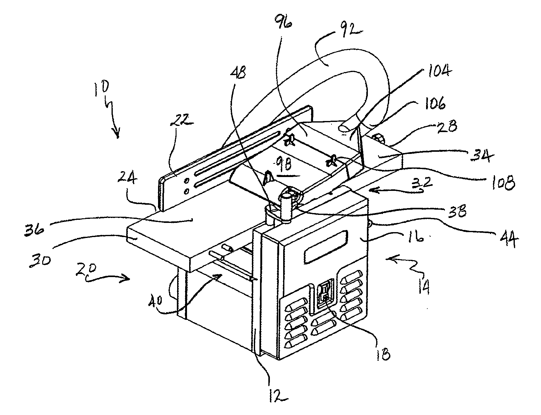
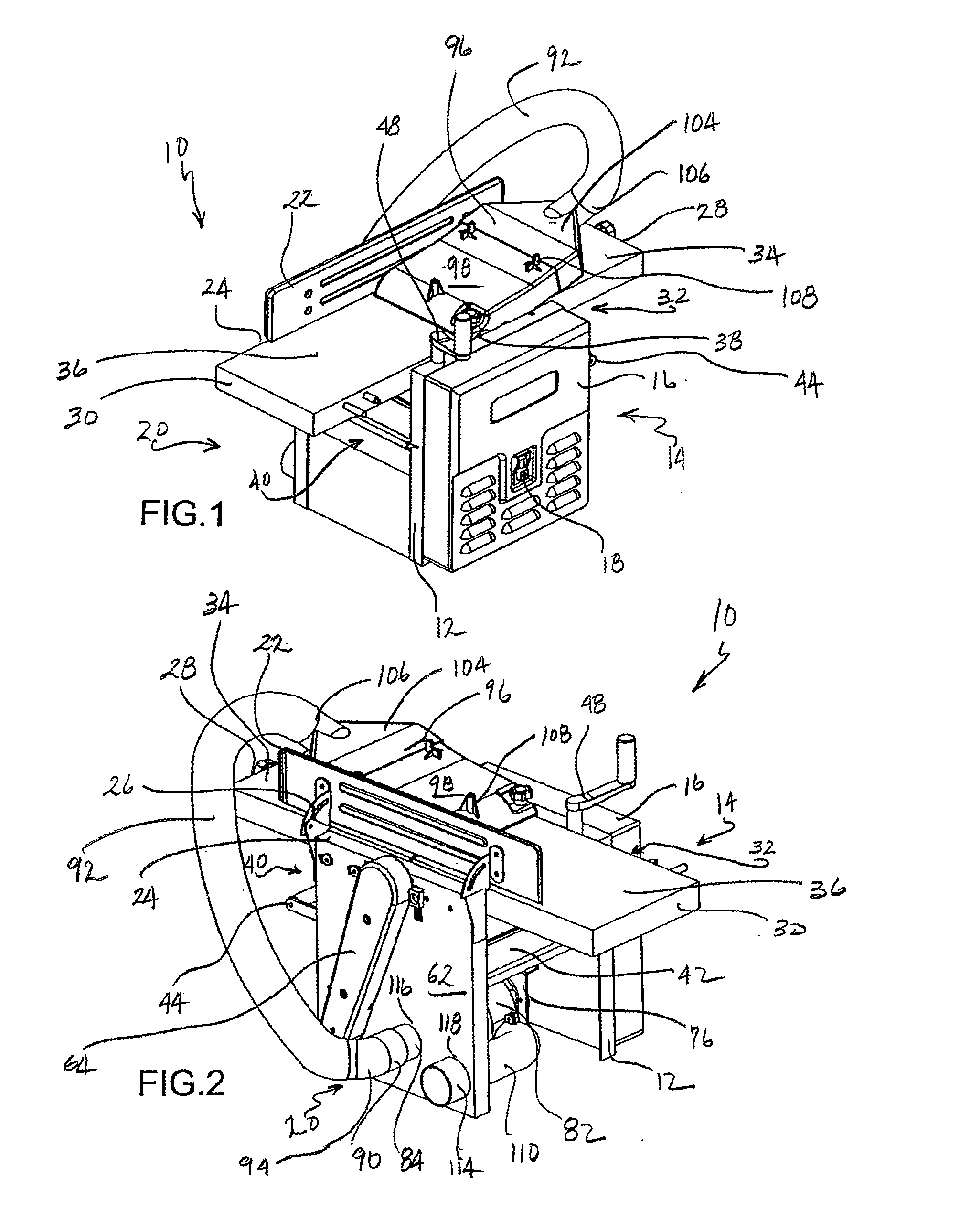
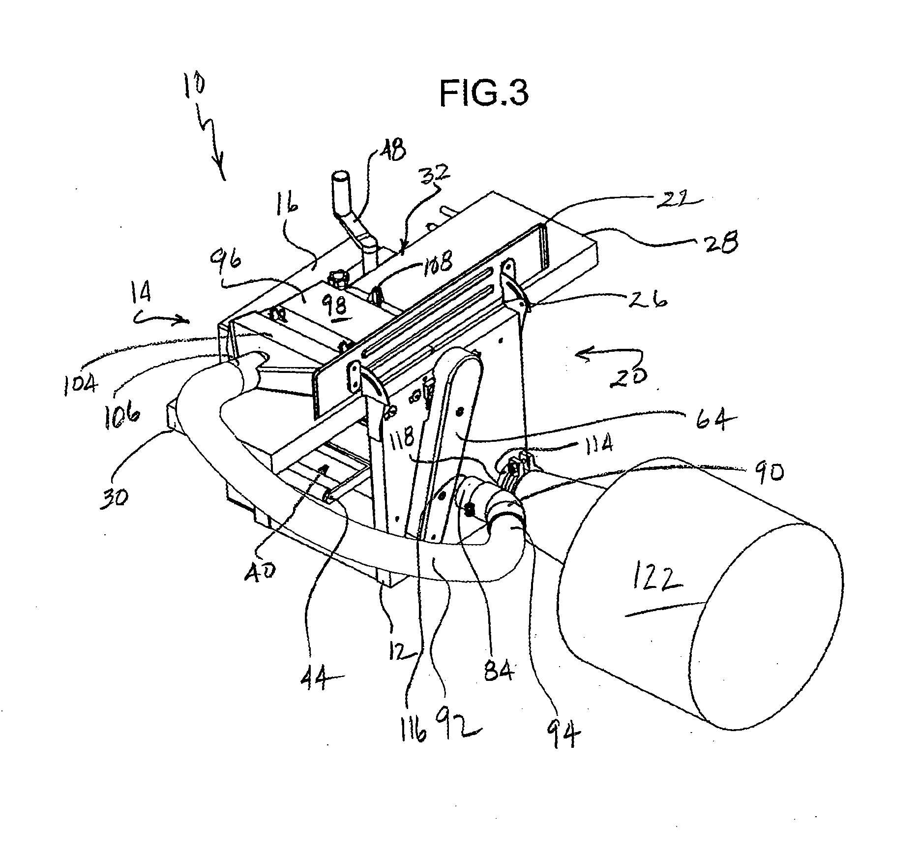
[0020]Referring now to FIGS. 1-4 and 9, the present jointer / planer is generally designated 10, and includes a machine frame 12 with a front side 14 having a shroud 16 and a control switch 18, a rear side 20 opposite the front side and having a fence 22 at an upper end 24. As is known in the art, the fence 22 is pivotable upon a pair of fence brackets 26 from a position parallel to the rear side 20 (as shown) to a position perpendicular to the rear side and projecting away from the rear side.

[0021]A board inlet end 28 is opposite a board outlet end 30, however depending on the application, boards may be inserted into the jointer / planer from either end. A jointer bed assembly 32 includes a first jointer bed 34 and a second jointer bed 36, the beds being separated by a rotary cutter 38 (FIG. 9) mounted transversely in the frame 12 and rotatably supported by bearings (not shown) as are known in the art. As is known in the art, the rotating cutter 38 rotates in an axis located transverse...


PUM


Abstract

A jointer/planer with an internal sawdust collection system, includes a machine frame having a board inlet end and a board outlet end, a rotating cutter mounted to the frame for rotation in an axis located transverse to a board feed direction, a dust collector hood disposable on the frame in a first position for jointing, and a second position for planing, a dust collecting impeller disposed in an impeller housing on the frame, a conduit having a first end in communication with the hood and a second end in communication with the impeller housing regardless of being in the first position or the second position, and a power source associated with the frame and constructed and arranged for powering the cutter and the impeller.

Description

BACKGROUND OF THE INVENTION[0001]The present application relates to powered woodworking machines, such as jointer / planers, and specifically to such machines having associated sawdust collection systems.[0002]In woodworking, jointers are used for providing a square or level edge to boards, and also for gradually reducing the thickness of stock wood to desired dimensions. Jointers are used with a fixed position, rotating cutter located between two adjacent jointer beds. One of the beds is fixed relative to the cutter, and the other bed is adjustable in height relative to the other and the fixed cutter to adjust the amount of material removed with each pass of the subject board. The user places the board upon the bed and pushes it over the cutter, which works the lower edge of the wood. A fence is typically provided to create a square edge.[0003]A planer is typically referred to as a wood leveling or reducing device used for cleaning up rough faces or creating uniform board thickness, ...

Claims


Application Information

Patent Timeline
IPC IPC(8): B23Q11/00B27C1/00B27G21/00
CPCB23Q11/0046B27G3/00B27C1/14B27C1/02
Inventor LIAO, CHIH HUNG
Owner LIAO CHIH HUNG
Why Eureka
Try Eureka