Method for detecting interference in radar system and radar using the same

a radar system and radar technology, applied in the field of radar system and radar interference detection, can solve the problems of unreliable range measurement obtained from a two-frequency cw radar in the presence of multiple target objects, interference between the fmcw radar with which the subject vehicle is equipped and the other radar installed in the other vehicle, and poor performance of two-frequency cw radar

Inactive Publication Date: 2009-04-16
DENSO CORP
View PDF3 Cites 44 Cited by
  • Summary
  • Abstract
  • Description
  • Claims
  • Application Information

AI Technical Summary

Benefits of technology

[0039]The reducing unit reduces the intensities of the exceptional frequency component to be smaller than or equal to the predetermined intensity threshold to remove influence of an obstacle located out of the radar range on detecting the event of interference.

Problems solved by technology

Unfortunately, the two-frequency CW radar performs poorly when there are multiple target objects at different ranges, and thus the range measurement obtained from a two-frequency CW radar in the presence of multiple target objects unreliable.
That is, interference between the FMCW radar with which the subject vehicle is equipped and the other radar Installed in the other vehicle may occur.
As a result of interference, it is hard to detect the beat frequencies accurately, and the distance to the target object such as the preceding vehicle or the relative speed of the target object cannot be accurately detected.
One of the reasons for difficulties in detecting such target characteristic accurately is that frequency spectrum characteristic of the beat signal contains a broad peak.
As a result, the peak frequency cannot be detected accurately for the beat frequency.
This results in an inaccurate detection of the target characteristic.
That is, the distance to the target object or the relative speed of the target object may be erroneously determined.
Hence, the conventional FMCW radars using the above mentioned fact may erroneously detect interference due to the existence of large or long obstacles located far beyond the measuring region of the FMCW radar.
Thus, large obstacles located far beyond the measuring region of the FMCW radar enhance the sum of intensities of the high frequency components and increase the number of frequency components which satisfy the predetermined conditions even if there are no other radars near, and result in erroneous determination of occurrence of interference between the FMCW radar and some other radar.
This determination may be a difficult task if any interference between the radar and some other radar occurs.
However, it is necessary to suspend the transmit operation to estimate the noise floor level and to detect occurrence of interference.
This means that during noise floor level estimation and Interference detection, any target characteristic such as presence of a target object within the measuring distance range of the radar system, distance between the radar system and the target object, and relative velocity of the target object to the radar system can not be determined.
This means that a continuous measurement of target characteristic can not performed.

Method used


Image

  • Method for detecting interference in radar system and radar using the same
  • Method for detecting interference in radar system and radar using the same
  • Method for detecting interference in radar system and radar using the same

Examples


first embodiment

[0085]Referring to FIGS. 1-16, a first embodiment and its modifications of the present invention will be discussed.

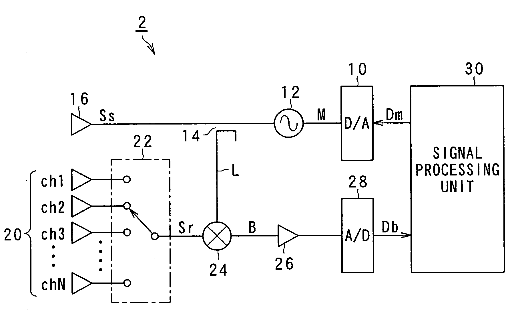
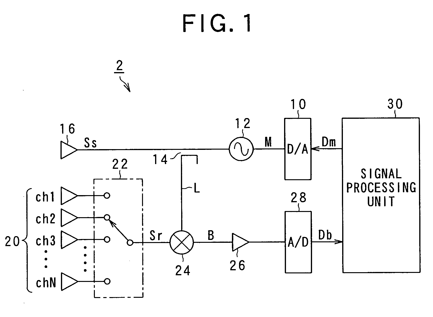
[0086]FIG. 1 is a block diagram showing a vehicle-mounted FMCW radar according to the present invention. The FMCW radar detects the distance to a target object located in a radar range (hereinafter it sometimes will be referred as to a “measuring distance range”) and / or a relative speed of the target object such as a preceding vehicle.

[0087]As shown in FIG. 1, the FMCW radar 2 includes a digital-analog (D / A) converter 10, an oscillator 12, a splitter 14, a transmitting antenna 16, and a signal processing unit 30.

[0088]The D / A converter 10 receives digital data Dm from the signal processing unit 30 and converts the received digital data Dm to an analog signal M. The oscillator 12 receives the analog signal M from the D / A converter 10 and thereby generates a radio frequency signal in the millimeter wave band, the frequency of the signal varying in time according to inform...

second embodiment

[0206]Referring to FIG. 17, a second embodiment of the present invention will be discussed.

[0207]FIG. 17 is a flow chart showing process for calculating the reference value according to the second embodiment of the present invention, the process including steps of identifying a peak frequency interval containing one of peak frequency components having a peak intensity larger than the predetermined threshold value in frequency spectrum characteristic of the beat signal, and replacing the peak Intensity with zero level in the intensity.

[0208]In this embodiment, operation at step S130 in FIG. 5 for calculating the first and the second reference values with respect to each of the frequency increasing section and the frequency decreasing section is modified from that in the first embodiment. So, in the following, operation for calculating the first and the second reference values according to the present embodiment will be explained.

[0209]In the present embodiment, the following operatio...

third embodiment

[0231]Referring to FIG. 18-19B, a third embodiment of the present invention will be discussed.

[0232]In this embodiment, operation at step S130 in FIG. 5 for calculating the first and the second reference values with respect to each of the frequency increasing section and the frequency decreasing section is modified from that in the first embodiment. So, in the following, operation for calculating the first and the second reference values according to the present embodiment will be explained.

[0233]FIG. 18 is a flow chart showing a process for calculating the integral value according to a third embodiment of the present invention, the process including steps of identifying a peak frequency interval containing one of the frequency components having intensity larger than the predetermined threshold value in frequency spectrum characteristic of the beat signal, and replacing the peak intensity with zero level in the intensity.

[0234]In the present embodiment, the following operation will ...


PUM


Abstract

A method for a radar for determining a level of interference of return of a radar wave transmitted by the radar from a target object and radio wave transmitted by some other radar, and a radar, in particular a frequency modulated continuous wave (FMCW) radar, that performs the method for determining the level of interference between the radar and some other radar is provided. In the method according to the present invention, after incident radio wave received by the radar is subjected by a frequency analysis to obtain frequency spectrum characteristic of the incident radio wave, one of frequency components of incident radio wave, the one of the frequency components having larger intensity than a predetermined intensity threshold value is not used to calculate a reference value that indicates the level of interference.

Description

CROSS REFERENCE TO RELATED APPLICATION[0001]The present application relates to and incorporates by reference Japanese Patent Applications 2007-72886 filed on Mar. 20, 2007.BACKGROUND OF THE INVENTION[0002]1. The Field of the Invention[0003]The present invention relates to a method for a radar for determining a level of interference between the radar and some other radar. The present invention further relates to an interference detecting device for a frequency modulated continuous wave (FMCW) radar and to the FMCW radar equipped with the interference detecting device using the method for determining the level of interference between the radar and some other radar.[0004]2. Description of the Prior Art[0005]A number of automotive radar systems which are suited to vehicle safety system, for example, crash protection systems that minimize the effects of an accident, reversing warning systems that warn the driver that the vehicle is about to back into an object such as a child or another ...

Claims


Application Information

Patent Timeline
Patent Type & Authority Applications(United States)
IPC IPC(8): G01S13/00
CPCG01S7/021G01S7/023G01S13/345G01S2013/9325G01S2013/0263G01S2013/9321G01S13/931
Inventor SAKAMOTO, MAI
Owner DENSO CORP
Why Eureka
Try Eureka