Imaging Device, Image Processing Device, and Program

Active Publication Date: 2009-04-16
NIKON CORP
View PDF10 Cites 70 Cited by
  • Summary
  • Abstract
  • Description
  • Claims
  • Application Information

AI Technical Summary

Benefits of technology

[0033]Moreover, in another embodiment of the present invention, a portrait photographic tone image by way of image proce

Problems solved by technology

Moreover, since a shooting lens with a large aperture diameter is large and expensive, in commonly used electronic cameras, a shooting lens with a small aperture diameter is used in many cases.
Therefore, the depth of field of a commonly used electronic camera tends to be deeper than that of the silver salt camera, thus, in many cases, it is difficult

Method used


Image

  • Imaging Device, Image Processing Device, and Program
  • Imaging Device, Image Processing Device, and Program
  • Imaging Device, Image Processing Device, and Program

Examples


first embodiment

Variation of First Embodiment

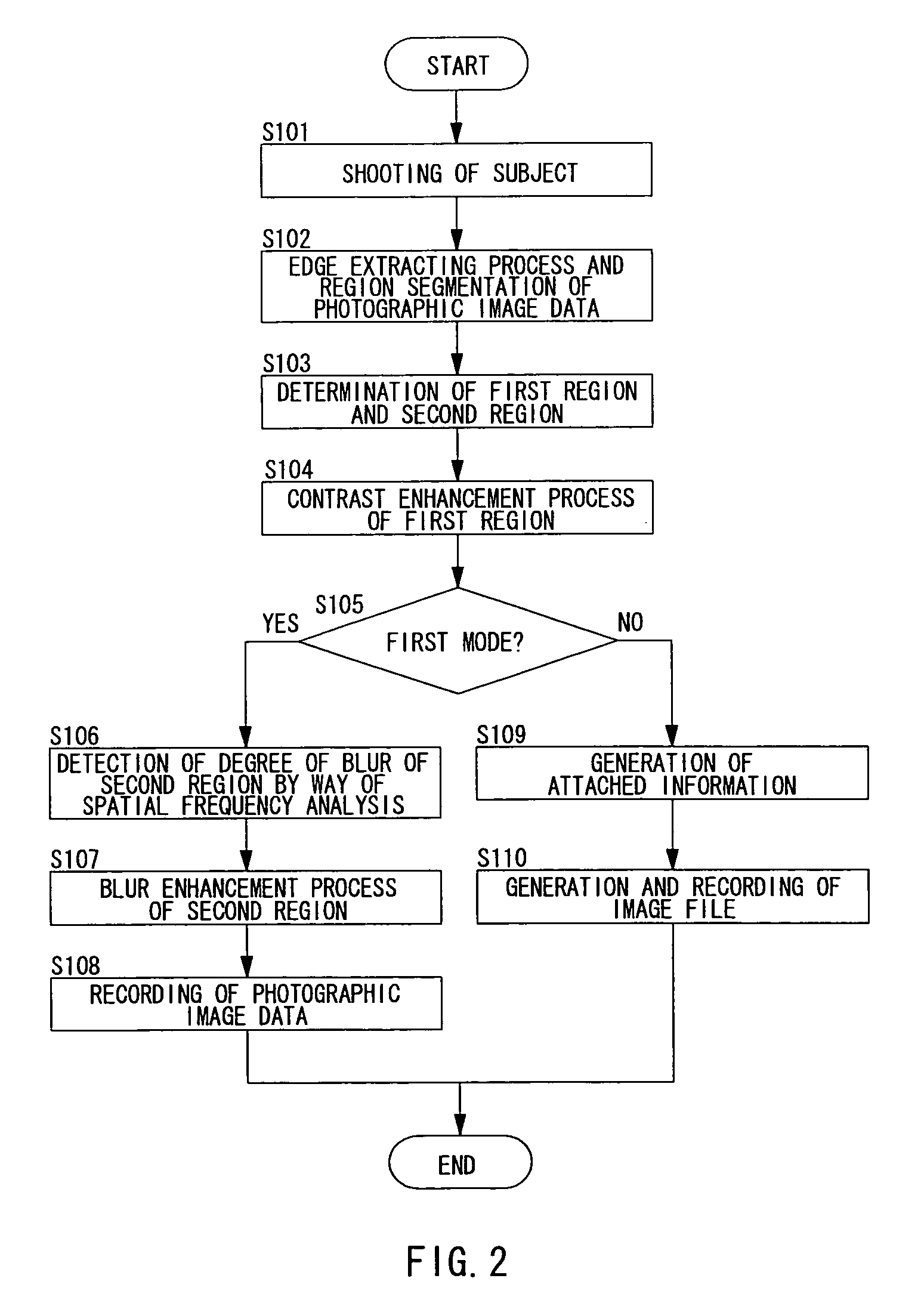
[0095]In the first embodiment, information of the degree of blur of an image is obtained by performing the DCT transform over the entire second region (S106). However, the CPU 22 may perform frequency analysis with respect to the outline portion of the image of the second region, and, based on the high frequency component of the outline portion in the second region, determine the degree of blur of the image.

[0096]As an example, based on the result of the edge extracting process (S102) by the image processing section 16, the CPU 22 specifies the outline portion of the second region. Then, the compressing / expanding processing section 17 performs DCT transform only on each of the pixel blocks containing the outline portion of the second region of the photographic image data. Then, the CPU 22 obtains the DCT coefficient of the outline portion of the second region as information of the degree of blur of the image. Of course, the CPU 22 may calculate the high ...

second embodiment

Description of Second Embodiment

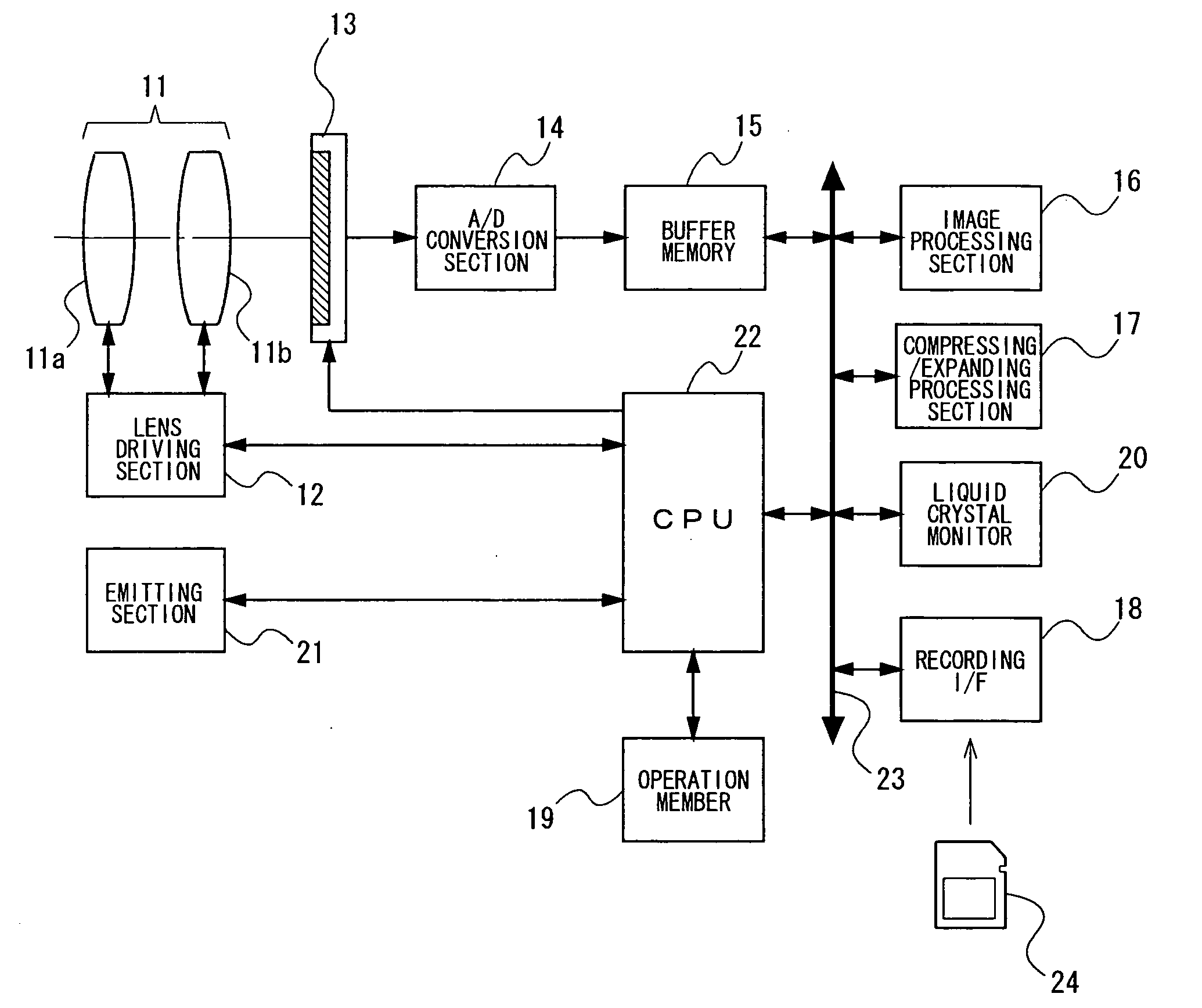
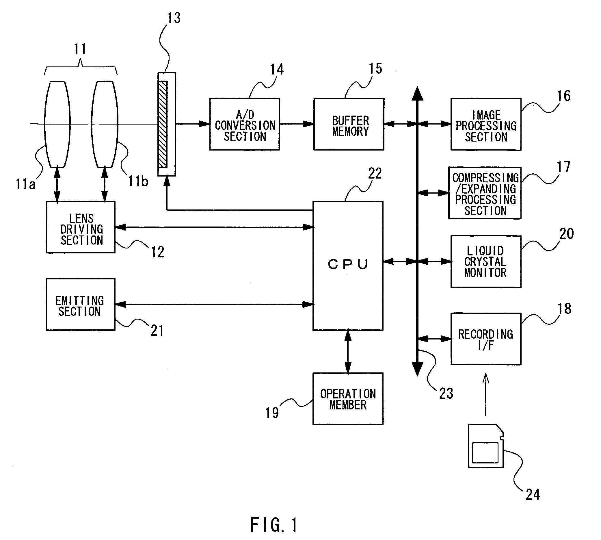
[0097]FIG. 10 is a flow chart illustrating operation in the “blur enhancement mode” of an electronic camera of a second embodiment. Here, in the second embodiment and a third embodiment, since the block diagrams of an electronic camera are common to that of FIG. 1, illustrations of them will be omitted in figures, and common configurations will be denoted by the same reference numerals, and their description will be omitted.

[0098]The second embodiment is a variation of the first embodiment, and differs from the first embodiment in that, as illustrated in FIGS. 11(a) to 11(c), the second region is further segmented into a plurality of sub-regions depending on the degree of blur, and the blur enhancement process is performed on the image of the second region for each of the sub-regions, respectively. In addition, since S201 to S205 in FIG. 10 correspond to S101 to S105 in FIG. 2, respectively, and S209 to S211 in FIG. 10 correspond to S108 to S110 in FI...

third embodiment

Description of Third Embodiment

[0103]FIG. 12 is a flow chart illustrating the operation in the “blur enhancement mode” of an electronic camera of a third embodiment.

[0104]The third embodiment is a variation of the first example, and differs from the first embodiment in that, based on first photographic image data shot with emitting light at an emitting section 21 and second photographic image data shot without emitting light, the image of first photographic image data is segmented into a first region and a second region. In addition, since S311 to S313 in FIG. 12 correspond to S108 to S110 in FIG. 2, respectively, duplicated descriptions thereof will be omitted.

[0105]Step S301: A user instructs an electronic camera to image a subject by way of full-pressing operation of a release button. The CPU 22 of the electronic camera images a subject image by causing the emitting section 21 to emit light and driving the image sensor 13 at the time of releasing. Then, based on the image signal ...


PUM


Abstract

An imaging device includes an imaging section, an image segmenting section, and a blur enhancement section. The imaging section images a field to generate photographic image data. The image segmenting section partitions an image of the photographic image data into a first region that is a main subject region and a second region where the main subject is not included. The blur detecting section detects degree of blur of an image of the second region of the image of the photographic image data. The blur enhancement section performs blur enhancement processing on the image of the second region to enlarge the degree of blur of the image after image processing in proportion to the magnitude of the detected degree of blur of the image.

Description

TECHNICAL FIELD[0001]The present invention relates to an imaging device etc. which images a field to generate photographic image data.BACKGROUND ART[0002]In portrait shooting or in close-up shooting of plants etc., photographic expression where a main subject is risen up by intentional blurring of the foreground or the background thereof, has been generally preferred. When such photographic expression is used, shooting is performed in a state where depth of the field is very shallow and the main subject is focused. Here, the depth of the field is determined depending on optical elements such as the aperture or the focal-length of a lens.[0003]On the other hand, the size of the exposure plane of an image sensor of a commonly used electronic camera is remarkably small as compared with that of the exposure plane (film) of a so-called silver salt camera. For this reason, if the same field angle as that of the silver salt camera is intended to be obtained, the focal-length of a shooting ...

Claims


Application Information

Patent Timeline
IPC IPC(8): H04N5/217H04N5/228G06T5/00H04N13/122
CPCG06T7/0081G06T2207/30201G06T5/008H04N5/23212G06T5/002H04N5/232G06T7/11H04N13/122H04N23/673H04N23/635H04N23/80
Inventor SAITO, IKUYA
Owner NIKON CORP
Why Eureka
Try Eureka