Load breaker arrangement

a load breaker and arrangement technology, applied in the direction of circuit-breaking switches, circuit-breaking switches for excess current, protective switch details, etc., can solve the problems of high temperature, high contact burn of switching contacts, and electrical arcs, and achieve the effect of low cos

Active Publication Date: 2009-04-16
SMA SOLAR TECH AG
View PDF8 Cites 187 Cited by
  • Summary
  • Abstract
  • Description
  • Claims
  • Application Information

AI Technical Summary

Benefits of technology

[0022]It is the object of the invention to find a low cost solution by means of which on the one side a DC current in a photovoltaic plant can be securely switched off, not only manually but also automatically in the event of a failure, and by means of which, on the other side, galvanic separation in at least one of the two current carrying lines of the DC current circuit is obtained.

Problems solved by technology

However, relays have the disadvantage that switching arcs occur, in particular when switching off the DC current.
This temporarily leads to high temperatures and to a high contact burn of the switching contacts.
As a result, the switching contacts can easily fuse together so that they virtually adhere together and are no longer capable of ensuring current interruption.
This risk however cannot be completely avoided.
The gates however have the disadvantage that they are quite big and also expensive.
This overcurrent protection function is slow.
A control of the switching contacts however is only possible with special remote control modules that are very expensive and are only sold for apparatus operating at high current or at high switching powers.
If cut off is to occur because of another event such as because a housing cover is opened, solutions with such apparatus are only to be realized for high currents and only at high cost and with considerable space occupancy.
For safety reasons, this is not acceptable though.
In case of only low currents, the protection may overheat.
A current interruption due to another event is not possible.
They are also suited for high switching currents and voltages such as several 100 A and several 100 V. However, they have the disadvantage of requiring much space and of high wiring expense.
Moreover, they can only be operated by hand so that they cannot be used for protecting functions such as overcurrent and also not for automatic enablement in other events.

Method used


Image

  • Load breaker arrangement
  • Load breaker arrangement
  • Load breaker arrangement

Examples


Embodiment Construction

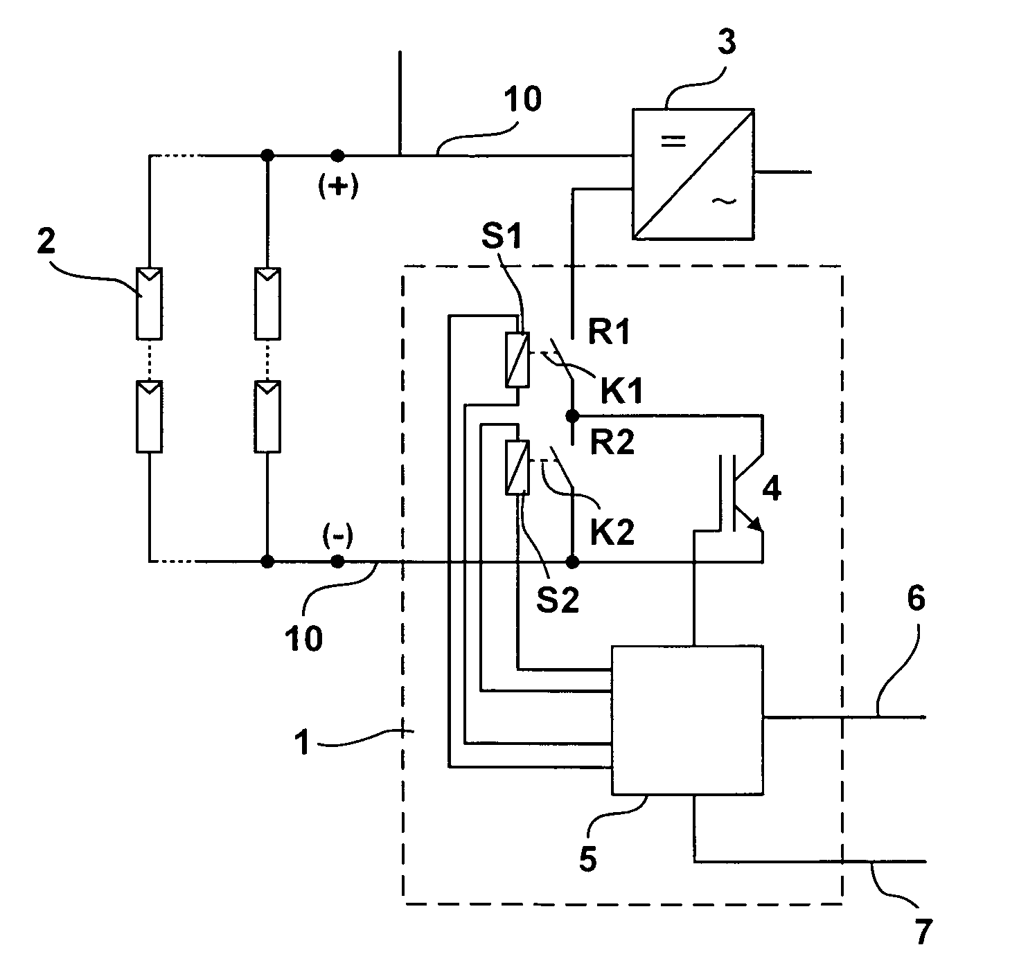
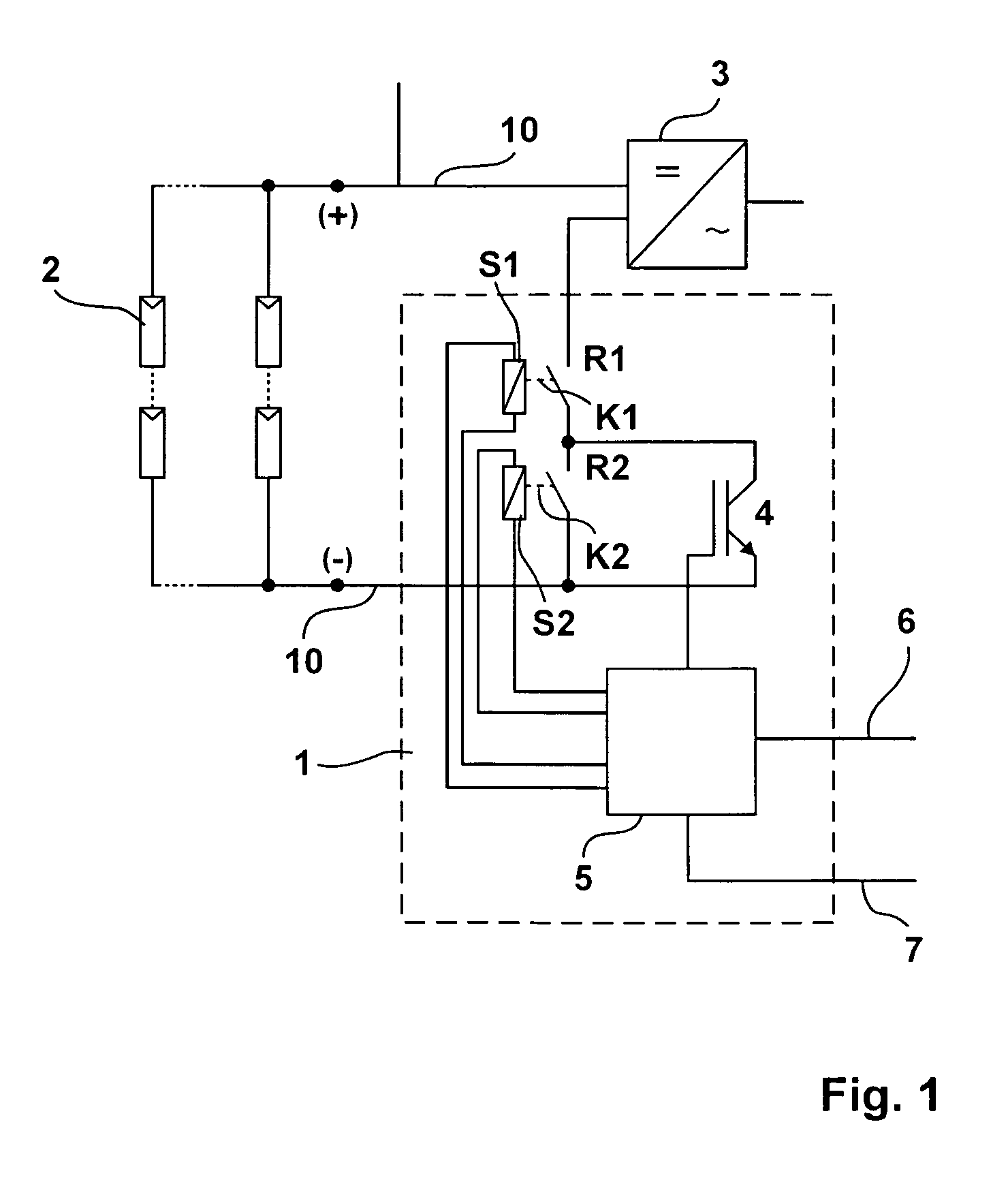
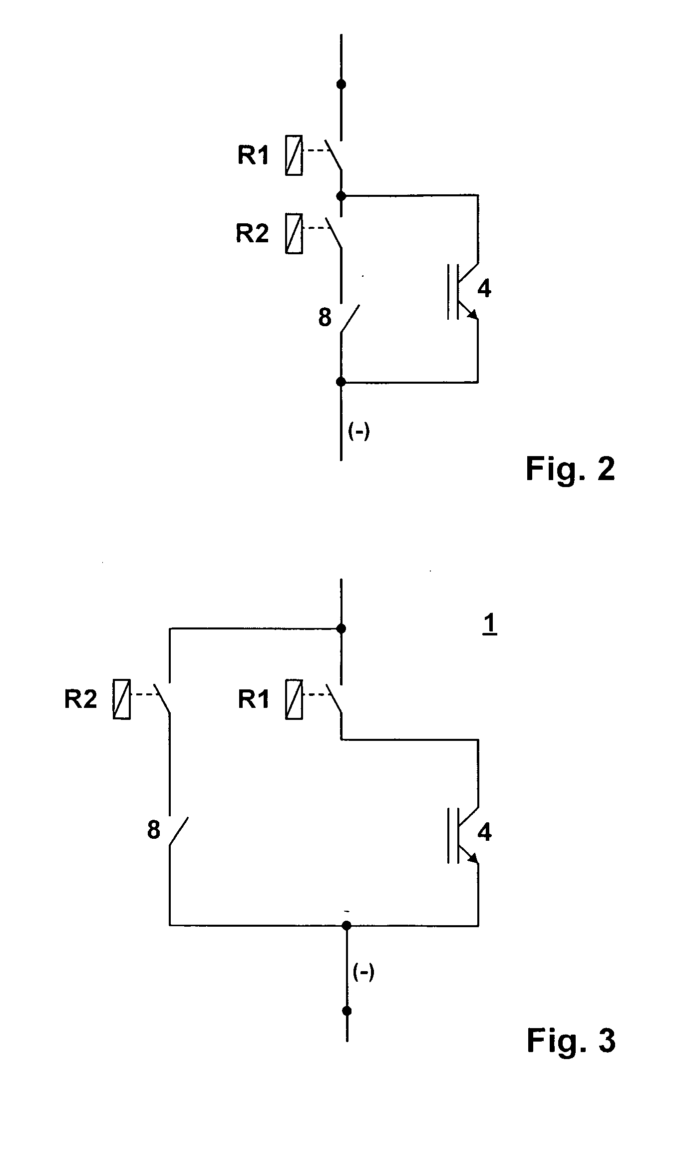
[0040]FIG. 1 illustrates a first example of a load breaker arrangement 1. This arrangement incorporates two relays R1 and R2. Each relay comprises a control coil S1, S2 with a switching contact K1, K2 or a pair of contacts. Both relays or more precisely both switching contacts K1, K2 are connected in series. For simplicity' sake, they will be referred to as relays.

[0041]A semiconductor switching element 4, in particular an IGBT switch, is connected in parallel to the relay.

[0042]The arrangement 1 lies in a DC current circuit with DC lines 10 between a photovoltaic generator 2, a photovoltaic plant and an inverter 3 or a DC / AC converter. If the photovoltaic generator 2 is added to the circuit of the inverter 3, the two relays R1, R2 are closed. Both relays are designed for being capable of carrying the needed load current in the closed condition.

[0043]Further, the arrangement 1 incorporates an electronic control unit 5 that is connected to the relays R1, R2 or to its control coils S1...


PUM


Abstract

The subject matter of the present invention is a load breaker arrangement (1) for switching on and off a DC current of a DC current circuit in a photovoltaic plant with a semiconductor switching element (4) to avoid a switching arc, there being provided an electronic control unit (5) configured such that one or more signals are received by the control unit, and the load breaker arrangement (1) being configured such that in at least one current-carrying line of the DC current circuit there is galvanic separation by a switching contact that is automatically controllable by the control unit (5) in the switched-off condition and one or more control signals being transmitted to the load breaker arrangement (1) and a semiconductor switching element (4) interrupting the DC current so that the switching contact is de-energized, whereby
    • the signals are flaw signals that are received in case of a flaw in the PV generator, inverter or on the AC side, the DC current circuit being automatically switched on or off by the control signals in case of at least one flaw,
    • said arrangement being configured such that, during switch off,
    • said semiconductor switching element (4) is at first closed in a first step,
    • the switching contacts (K1, K2) of a first switching means are opened in a second step for the DC current to flow through said semiconductor switching element (4),
    • said semiconductor switching element (4) being again opened in a third step and
    • switching contacts (K1, K2) of a second switching means being opened in order to cause galvanic separation to occur
    • and that an additional manually operable load breaker (8) is connected, said manually operable load breaker (8) being a manually breakable DC current connecting system with plug contacts for photovoltaic plants that is provided with an electronic arc quenching system.

Description

CROSS-REFERENCE TO RELATED APPLICATIONS[0001]This application claims Priority from European Application No. EP 07019985.6 filed on Oct. 12, 2007BACKGROUND OF THE INVENTION[0002]1. Field of the Invention[0003]The invention relates to a load breaker arrangement for switching a DC current of a DC current circuit on and off in a photovoltaic plant with a semiconductor switching element for preventing a switching arc, there being provided an electronic control unit configured such that one or more signals are received by the control unit and the load breaker arrangement being configured such that in at least one current-carrying line of the DC current circuit there is a galvanic separation by a switching contact that is automatically controllable by the control unit in the switched-off condition and that one or more control signals at the load breaker arrangement are passed to the load breaker arrangement and a semiconductor switch element interrupting the DC current for the switching co...

Claims


Application Information

Patent Timeline
Patent Type & Authority Applications(United States)
IPC IPC(8): H01H9/30H02H3/00
CPCH01H9/542Y02E10/50H01L31/02021H01H33/596H01H71/00
Inventor BREMICKER, SVENBUCHHOLD, STEFANGREIZER, FRANKCRAMER, GUNTHER
Owner SMA SOLAR TECH AG
Why Eureka
Try Eureka