Drive device for vehicle

a technology for driving devices and vehicles, applied in electric propulsion mounting, transportation and packaging, gearing, etc., can solve the problems of increased vehicle length, increased vehicle width, and increased likelihood of vehicle collisions, and achieves small flow cross-sectional surface area and great flow rate

Inactive Publication Date: 2009-04-16
TOYOTA JIDOSHA KK
View PDF0 Cites 56 Cited by
  • Summary
  • Abstract
  • Description
  • Claims
  • Application Information

AI Technical Summary

Benefits of technology

[0046]With the vehicular drive apparatus recited in claim 3, the second electric motor is disposed on the first axis between the differential portion and the drive linkage. This enables a member on a first shaft and another member on a second shaft to be close to each other in an axial size, making it possible to obtain a downsized vehicular drive apparatus as a whole.
[0076]With the vehicular drive apparatus recited in claim 32, the longitudinal path of the second input shaft may preferably extend to a lubricating area of the drive gear to allow lubricating oil to be supplied to the longitudinal path of the second input shaft via the lubricating oil passage formed in the casing portion in bifurcated flows to the drive gear side and the differential mechanism side. This makes it possible for the drive gear and the differential mechanism to be adequately supplied with lubricating oil at relatively great flow rates even if the longitudinal flow passage of the second input shaft has a relatively small flow cross-sectional surface area.

Problems solved by technology

In installing such component parts, there are supposedly disadvantages such as an increase in vehicle length and an increase in vehicle width.
Especially, with a transverse-mounted layout adopted for an FF vehicle or RR vehicle, installation airspace is limited; causing likelihood to occur with a further increase in difficulties being encountered.
Moreover, among the increased number of component parts, the electric motor and the transmission, having increased limitations on installations, are independently assembled and resulting in likelihood of a remarkable drop in assembling characteristic.
However, no layout technology for such a vehicular drive apparatus incorporating the first electric motor, the differential device, the second electric motor and the transmission has been absolutely known.
Even if the drive apparatus taking a rowed structure formed on a plurality of axes, depending on how the component parts are located or how a housing is split, a difficulty has been encountered in minimizing an axial size of the drive apparatus without increasing the number of parallel shafts and accommodating the component parts in a limited vehicle width.
Thus, if lubricating oil is supplied from the axial end of the rotary shaft, the rotary shaft must have an increased outer diameter and an in-shaft oil passage must have an increased cross-sectional surface area, otherwise inadequate lubrications occur in the component parts in lubricating areas placed on a downstream side of a flow of lubricating oil.
Further, no layout technology on the vehicular drive apparatus including the first electric motor, the differential portion, the second electric motor and the transmission portion has been absolutely known.
Even if the drive apparatus is merely formed in a multiple-row structure, an issue arises with a difficulty encountered in adequately minimizing an axial dimension of the drive apparatus depending on a layout of the component parts and how the housing is split.
Thus, a remarkable drop occurs in assembling characteristic with a resultant deterioration in workability.
This causes an issue to arise with the occurrence of an increase in a resultant heat value.
Thus, it becomes relatively difficult to provide a lubricating oil passage for lubricating oil to be supplied to an oil passage longitudinally extending through the rotary shaft.
If an attempt is made to form a lubricating oil passage in a cover, forming part of a housing, in an area opposite to the engine to supply lubricating oil from an axial end of the input shaft, the cover becomes complicated in structure with a resultant complicated structure in connection up to a first shaft.

Method used


Image

  • Drive device for vehicle
  • Drive device for vehicle
  • Drive device for vehicle

Examples


embodiment 1

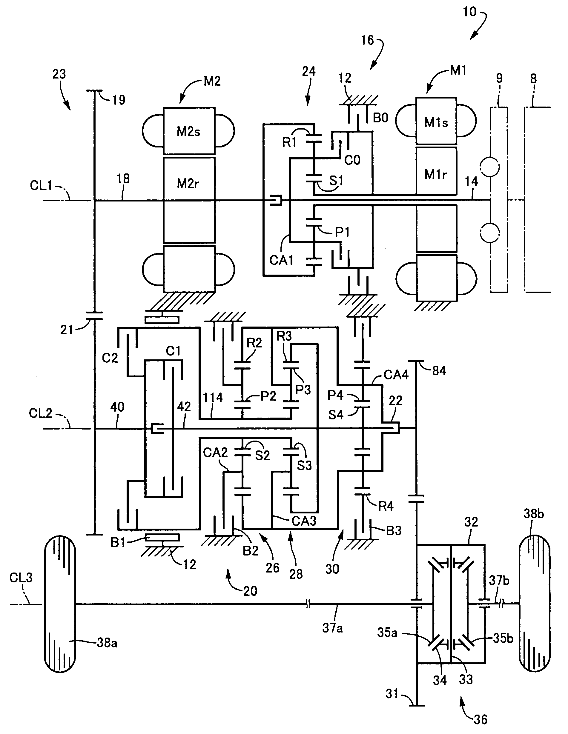
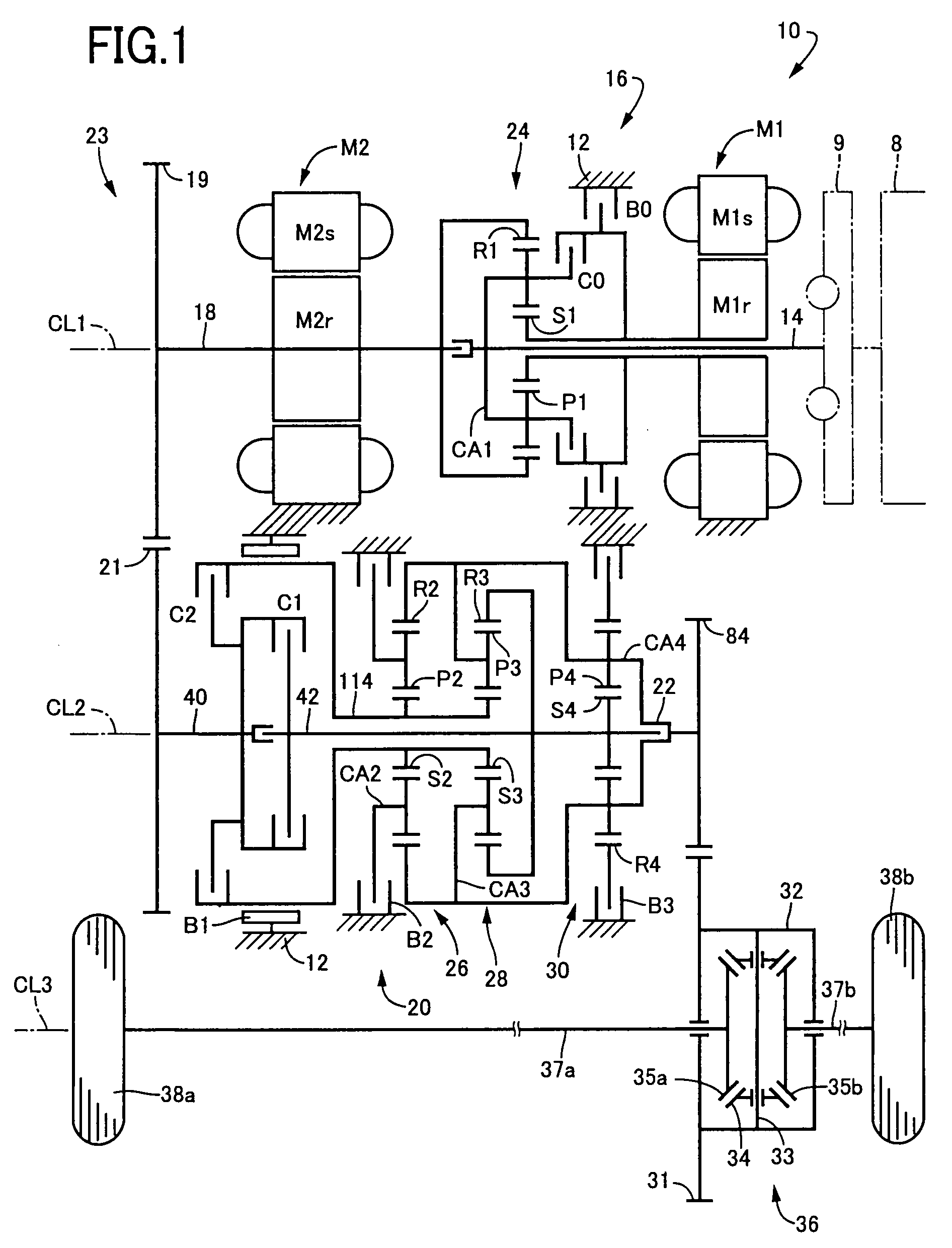
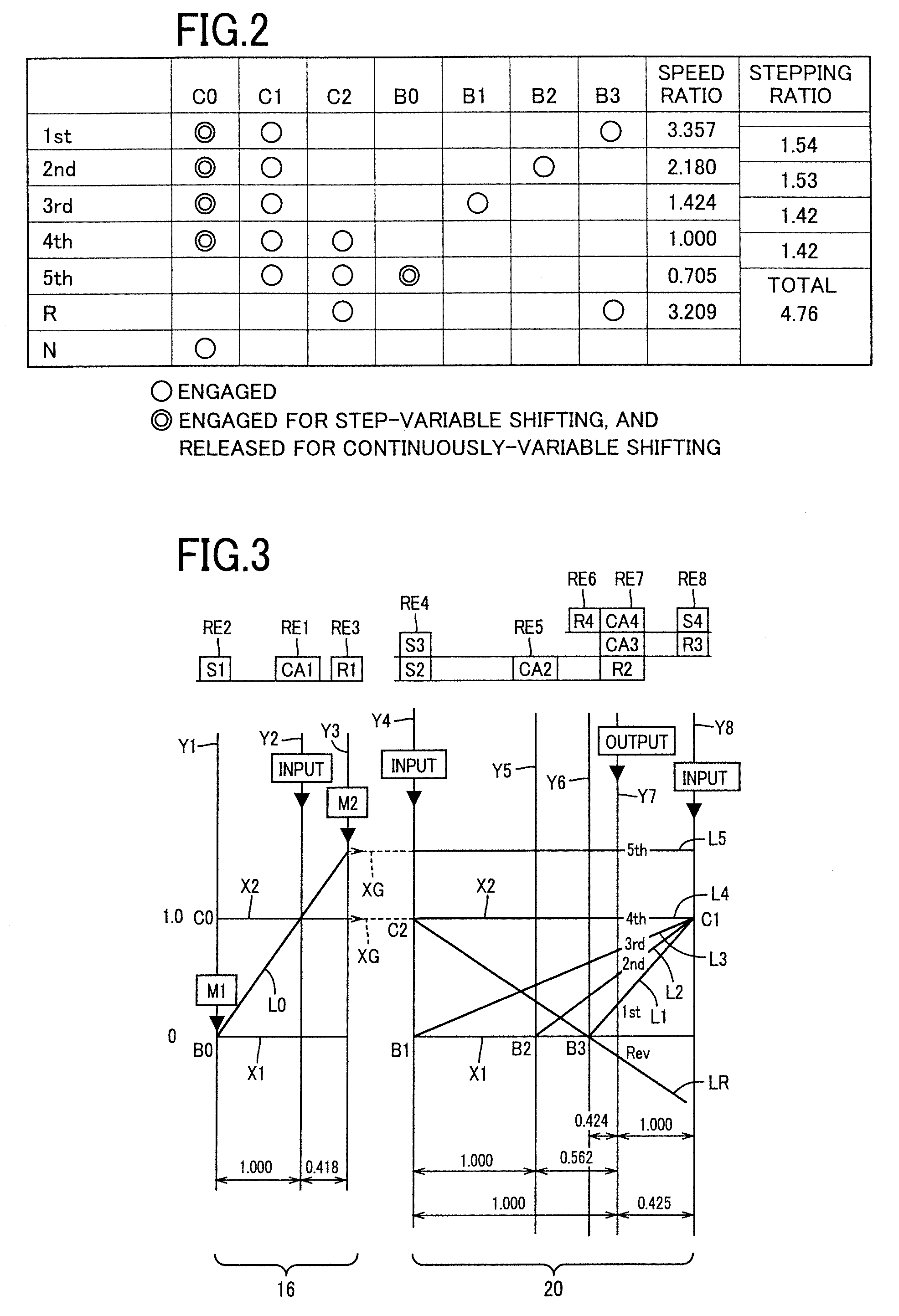
[0151]Referring first to the schematic view of FIG. 1, there is shown a drive apparatus 10 for a hybrid vehicle, which is constructed according to one embodiment of this invention. The drive apparatus 10 shown in FIG. 1 includes: an engine 8; a transaxle housing 12 (hereinafter referred to simply as “housing 12”), which is a stationary member attached to the body of the vehicle; a pulsation absorbing damper (vibration damping device) 9; a first input shaft in the form of an input rotary member 14 connected to the engine 8 through the pulsation absorbing damper 9 and receiving an output of the engine 8 through the pulsation absorbing member 9; a first electric motor M1; a hydraulically operated differential limiting device in the form of a switching clutch C0 and a switching brake B0; a differential gear mechanism or differential portion in the form of a power distributing mechanism 16 connected to the input rotary member 14; a power transmitting member 18 disposed downstream of the ...

embodiment 2

[0272]There will be described other embodiments of the present invention. In the following description of the other embodiments, the same reference signs as used in the first embodiment will be used to identify the functionally identical elements, redundant description of which is omitted.

[0273]Referring to the fragmentary cross sectional view of FIG. 19, there is shown a part of a vehicular drive apparatus 186 according to the second embodiment of this invention. This drive apparatus 186 is different from the drive apparatus 10 of the first embodiment, only in that a drive linkage 188 is provided in place of the drive linkage 23. As shown in FIG. 19, the drive linkage 188 includes a drive sprocket 190, a driven sprocket 192, and a connecting belt 194 which is formed of a metal or resin and which connects the drive and driven sprockets 190, 192. The drive sprocket 190 is mounted on the axial end portion of the power transmitting member 18 through the connecting member 118 such that ...

embodiment 3

[0275]Referring next to the fragmentary cross sectional view of FIG. 20, there is shown a part of a vehicular drive apparatus 196 according to the third embodiment of the invention. This drive apparatus 196 is different from the drive apparatus 10 of the first embodiment, in that the axial position of the engine 8 is opposite to that in the first embodiment, and in that an idler gear 200 is interposed between the differential drive gear 84 and the large-diameter gear 31 of the final reduction gear device 36. The idler gear 200 is rotatably supported by the first and second casing portions 12a, 12b, via bearings 198. In the present third embodiment, a fourth axis CL4 is provided between and in parallel to the second and third axes CL2, CL3, and the idler gear 200 is supported rotatably about the fourth axis CL4, in meshing engagement with the differential drive gear 84 and the large-diameter gear 31 of the final reduction gear device 36. The idler gear 200 transmits a rotary motion f...


PUM


Abstract

A miniaturized vehicular drive apparatus is provided with a reduced size in an axial direction without increasing the number of parallel shafts. A first electric motor M1 and a power distributing mechanism (differential portion) 16 are disposed on a first axis CL1, forming a rotational axis of an input rotary member 14, in series starting therefrom and an automatic transmission (transmission portion) 20 is disposed on a second axis CL2 parallel to the first axis CL1. A drive linkage 23 is provided between a power transmitting member 18, acting as a rotary member placed on the first axis CL1 at an end portion thereof in opposition to the input rotary member 14, i.e., in opposition to an engine 8, and a first intermediate shaft (rotary member) 40, disposed on the second axis CL2 at an end portion thereof in opposition to the input rotary member 14, for power transmitting capability. Thus, a power transmitting path is formed in a C-shape, i.e., a U-shape with a reduction in size of the axial direction, enabling the miniaturization to provide a simplified structure without increasing the number of parallel shafts.

Description

TECHNICAL FIELD[0001]The present invention relates to a vehicular drive apparatus having a first electric motor, a differential device, a second electric motor and a transmission, a vehicular drive apparatus having an electric motor, a differential portion and a differential drive gear or a vehicular drive apparatus having an input shaft, an electric motor, a differential portion and a transmission portion. More particularly, it relates to a technology of miniaturizing a vehicular drive apparatus in an axial dimension while improving assembling capability, a technology of increasing cooling characteristic of an electric motor and a technology of simplifying a hydraulic circuit structure.BACKGROUND ART[0002]There has been known a vehicular drive apparatus having a first electric motor, a differential device, a second electric motor and a transmission. For instance, a hybrid vehicular drive apparatus, disclosed in Patent Publication 1, represents such a drive apparatus. With such an a...

Claims


Application Information

Patent Timeline
Patent Type & Authority Applications(United States)
IPC IPC(8): F16H48/06F16H3/72F16H57/04B60W20/00B60K6/365B60K6/445B60L50/16
CPCB60K1/02B60L2270/30B60K6/387B60K6/40B60K6/445B60K6/48B60K6/547B60L11/14F16H3/728F16H57/043F16H57/0471F16H57/0484F16H2037/0873F16H2200/0043F16H2200/0047F16H2200/2007F16H2200/201F16H2200/2023F16H2200/2046F16H2200/2048Y02T10/6221Y02T10/7077Y02T10/6239Y02T10/70B60K6/365B60L50/16Y02T10/62Y02T10/7072
Inventor TABATA, ATSUSHIMIYAZAKI, TERUFUMIKAMADA, ATSUSHITAGA, YUTAKA
Owner TOYOTA JIDOSHA KK
Why Eureka
Try Eureka