Multi-stage system for verification of container contents
What is Al technical title?
Al technical title is built by PatSnap Al team. It summarizes the technical point description of the patent document.
a multi-stage system and container technology, applied in the direction of instruments, machines/engines, measurement with semiconductor devices, etc., can solve the problem of false alarm generation of radiation detection systems
Inactive Publication Date: 2009-04-23
S2 PHOTONICS LLC +1
View PDF44 Cites 11 Cited by
Summary
Abstract
Description
Claims
Application Information
AI Technical Summary
This helps you quickly interpret patents by identifying the three key elements:
Problems solved by technology
Method used
Benefits of technology
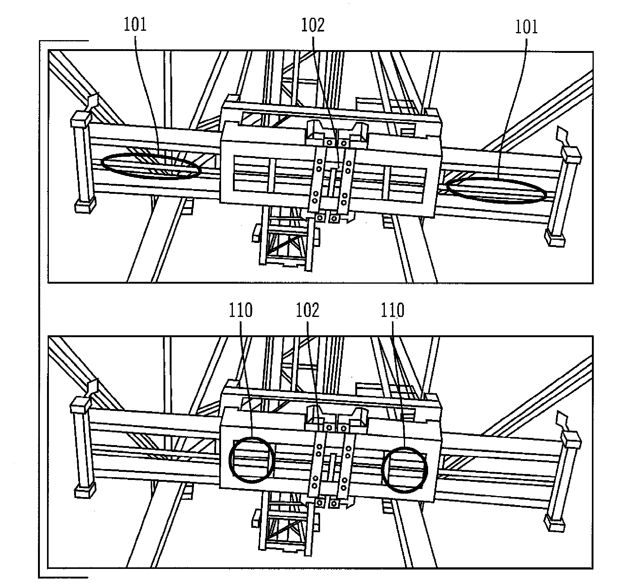
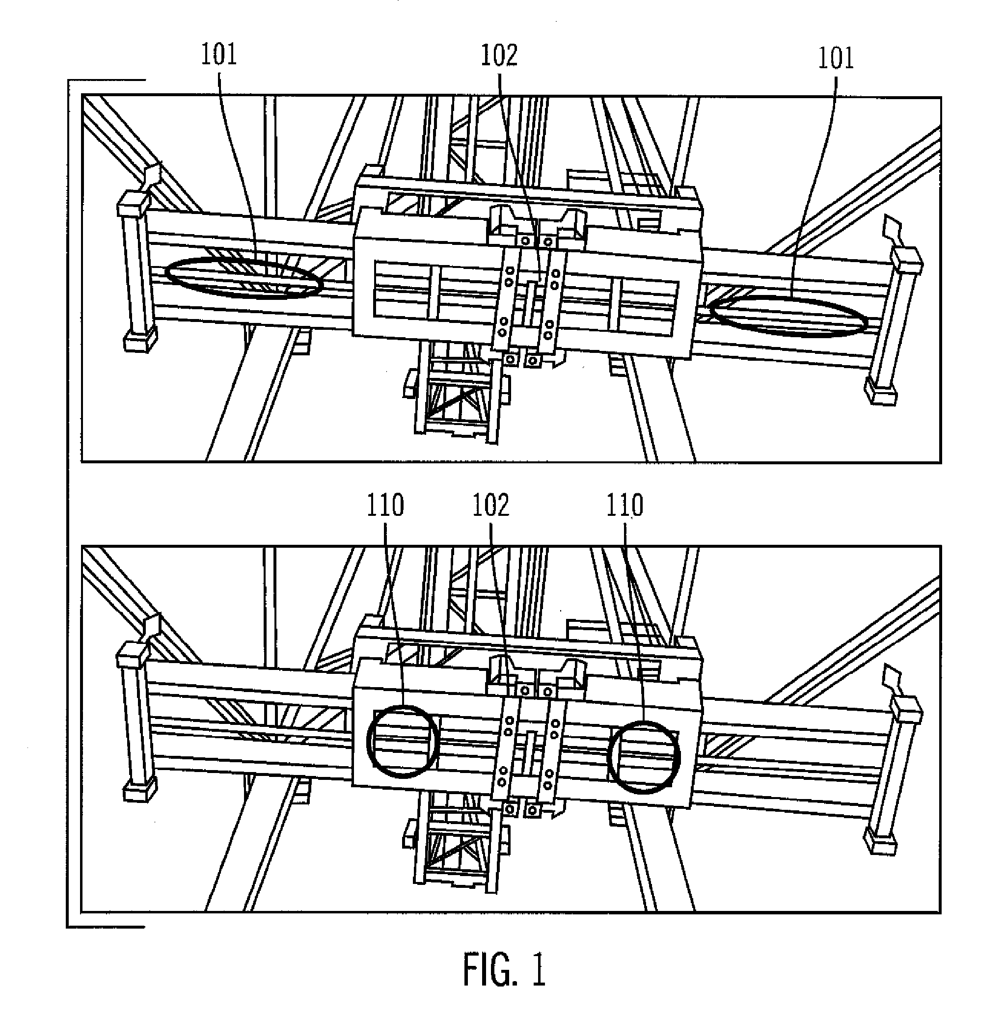
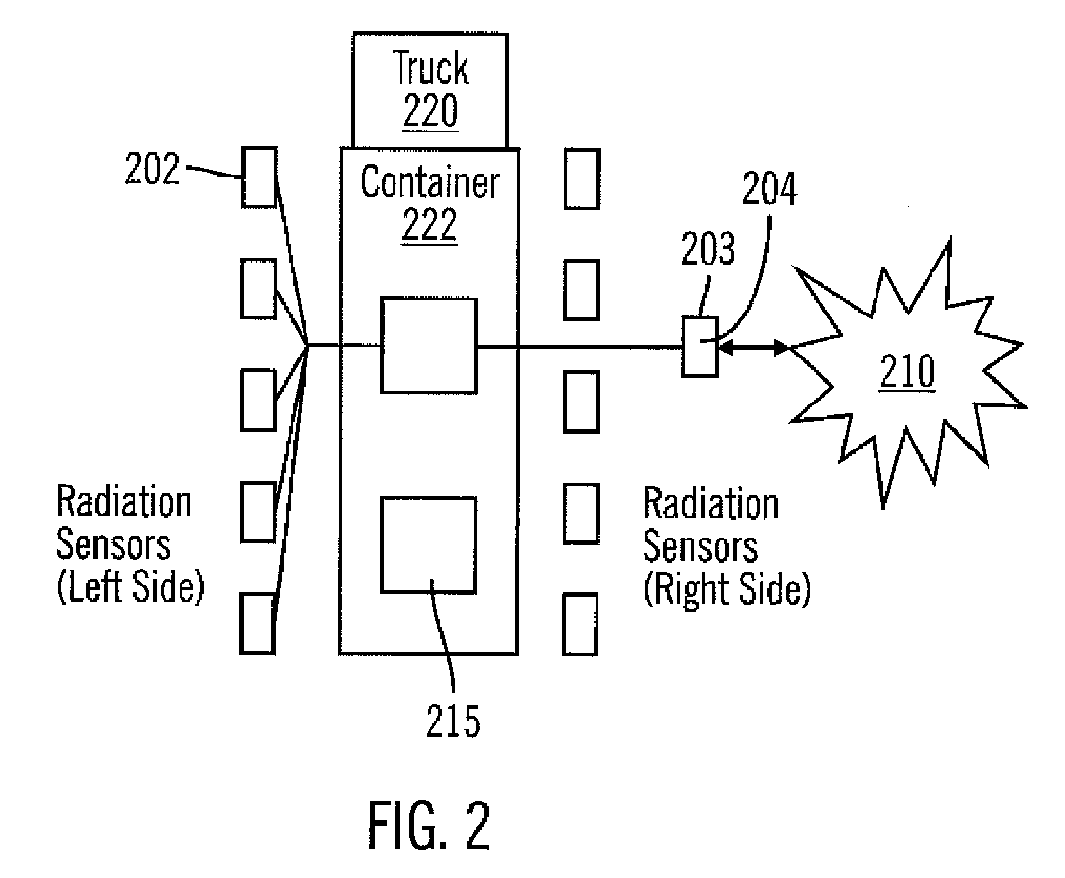
[0007]According to an embodiment of the present invention, a multi-stage detection system and method detects gamma and neutron radiation providing additional data capture times when radiological materials are detected and a secondary position for further analysis. The gamma and neutron detectors mounted on the spreader bar of a gantry crane provide an initial identification of the presence of radiological materials within a shipping container. The spreader bar typically provides up to 30 seconds of close proximity for the radiation sensors to analyze the shipping container. The radiation data captured is analyzed for specific isotope identification. Should the system require more data to complete the analysis, the spreader bar contact with the shipping container is extended to enable additional data capture. Furthermore, if the shipping container requires further analysis time to determine the specific isotopes present, an embodiment of the present invention provides a secondary radiation analysis position comprised of an array of radiation sensors deployed to allow the targeted container to be further analyzed. The present invention, according to an embodiment, allows an extended time for radiation analysis for those shipping containers where radiological materials have been detected and where the normal flow of the gantry crane movement does not allow for a complete analysis. Additionally, an embodiment of the present invention provides for a secondary radiation analysis position where the additional time for analysis is required beyond that provided at the gantry crane, Another embodiment provides for tracking and monitoring of the targeted shipping container as it moves from the spreader bar to the secondary radiation analysis position.
[0010]By identifying the specific isotope(s) that are present allows the system to also identify the types of goods or materials that the isotopes represent. With a list of potential goods that represent the identified isotopes, the system can perform a comparison between the identified goods or materials and the shipping container manifest to determine if the radiological material(s) present match the expected materials within the container. The process of 1) identifying the isotope(s) that are within a container, 2) identifying the goods or materials that the isotopes represent and 3) verifying the contents of the manifest against the identified goods, allows the efficient verification of the container without negative impact to the flow of commerce
[0017]A user interface of the information processing system, according to an embodiment, provides a graphic view of the radiation spectra detected and the isotopes identified. The user interface allows a user of the system to view, among other things, the individual detectors, detector groups, individual sensors, and sensor groups, individual nodes and a combination of multiple nodes to quickly identify maintenance conditions, radiation detected, and isotopes identified.
Problems solved by technology
Many normally occurring radiological materials exist in common goods and cause radiation detection systems to produce false alarms.
Method used
Image
Click on the blue label to locate the original text in one second.
Reading with bidirectional positioning of images and text.
Examples
Embodiment Construction
[0027]While the specification concludes with claims defining the features of the invention that are regarded as novel, it is believed that the invention will be better understood from a consideration of the following description in conjunction with the drawing figures, in which like reference numerals are carried forward. It is to be understood that the disclosed embodiments are merely exemplary of the invention, which can be embodied in various forms. Therefore, specific structural and functional details disclosed herein are not to be interpreted as limiting, but merely as a basis for the claims and as a representative basis for teaching one of ordinary skill in the art to variously employ the present invention in virtually any appropriately detailed structure. Further, the terms and phrases used herein are not intended to be limiting; but rather, to provide an understandable description of the invention.
[0028]The terms “a” or “an”, as used herein, are defined as one, or more than ...
PUM
Abstract
A multi-stage process utilizing one or more radiation sensors on a distributed network for the detection and identification of radiation, explosives, and special materials within a shipping container. The sensors are configured as nodes on the network. The system supports extended time options at each node and the ability to combine data from multiple nodes for the data acquisition and analysis of shipping containers. The system collects radiation data from one or more nodes and compares the collected data to one or more stored spectral images representing one or more isotopes to identify one or more isotopes present. The identified one or more isotopes present are corresponded to possible materials or goods that they represent. The possible materials or goods are compared with the manifest relating to the container to confirm the identity of materials or goods contained in the container or to detect and / or identify unauthorized materials or goods in the container. The containers are monitored and tracked as they are moved between the nodes. A central monitoring station monitors the radiological sensors, the information from the nodes and the tracking of the shipping containers. For shielded materials, explosives and other types of material detection, a neutron pulse device could be incorporated into the spreader bar position, the secondary position or both.
Description
CROSS-REFERENCE TO RELATED APPLICATIONS[0001]This application is based on, and claims priority from, prior co-pending U.S. Provisional Patent Application No. 60 / 759,332, filed on Jan. 17, 2006, by inventor David L. FRANK, and entitled “Sensor Interface Unit And Method For Automated Support Functions For CBRNE Sensors”; and further is based on, and claims priority from, prior co-pending U.S. Provisional Patent Application No. 60 / 759,331, filed on Jan. 17, 2006, by inventor David L. FRANK, and entitled “Method For Determination Of Constituents Present From Radiation Spectra And, If Available, Neutron And Alpha Occurrences”; and further is based on, and claims priority from, prior co-pending U.S. Provisional Patent Application No. 60 / 759,373, filed on Jan. 17, 2006, by inventor David L. FRANK, and entitled “Distributed Sensor Network with Common Platform for CBRNE Devices; and further is based on, and claims priority from, prior co-pending U.S. Provisional Patent Application No. 60 / 759...
Claims
Application Information
Patent Timeline
Application Date:The date an application was filed.
Publication Date:The date a patent or application was officially published.
First Publication Date:The earliest publication date of a patent with the same application number.
Issue Date:Publication date of the patent grant document.
PCT Entry Date:The Entry date of PCT National Phase.
Estimated Expiry Date:The statutory expiry date of a patent right according to the Patent Law, and it is the longest term of protection that the patent right can achieve without the termination of the patent right due to other reasons(Term extension factor has been taken into account ).
Invalid Date:Actual expiry date is based on effective date or publication date of legal transaction data of invalid patent.
Patent Type & Authority Applications(United States)