
Laser module package and display apparatus using the same

a laser module and display device technology, applied in semiconductor lasers, instruments, optics, etc., can solve the problems of not being able to help generating the laser beam, the outputted green laser beam is unstably vibrated, and the previously manufactured green laser module cannot generate the original outputted green laser beam. to achieve the effect of maximizing the operation temperature range of the laser modul

Inactive Publication Date: 2009-04-23
SAMSUNG ELECTRO MECHANICS CO LTD
View PDF0 Cites 6 Cited by
  • Summary
  • Abstract
  • Description
  • Claims
  • Application Information

AI Technical Summary

Benefits of technology

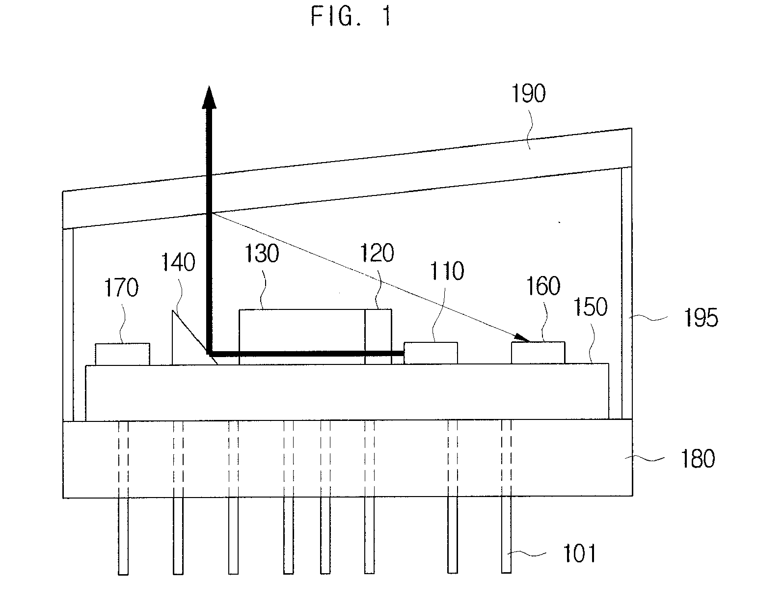
[0013]Accordingly, the present invention provides a laser module package and a display apparatus using the same that can maximize an operation temperature range of a laser module by regularly maintaining the operation temperature of elements included in the laser module by use of a micro heater or a thermoelectric element.
[0014]The present invention also provides a laser module package and a display apparatus using the same that can largely reduce power consumption, volume and manufacture cost by using a micro heater or a thermoelectric element working in a heating mode mounted in the package to constantly maintain the operation temperature of a laser module.
[0029]Here, the operation temperatures of the laser medium and the optical crystal can be maintained as a substantially same temperature as the target temperature by allowing the laser medium and the optical crystal to be placed together on the thermoelectric element.

Problems solved by technology

At this time, while the red or blue color light source can employ a single laser diode to emit a red or blue color beam of light, it is not easy to manufacture a single laser diode to emit a green color beam of light on commercial business.
This may make it impossible for the previously manufactured green laser module to generate the originally desired outputted green laser beam and make the outputted green laser beam unstably vibrated.
Also, since the wavelength of the laser beam generated by each laser module having different sensibility is differently changed according to the foregoing change of the operation temperature, the red or blue laser module package can not help generating the laser beam having the wavelength that is differentiated according to the change of the operation temperature as well.

Method used


Image

  • Laser module package and display apparatus using the same
  • Laser module package and display apparatus using the same
  • Laser module package and display apparatus using the same

Examples


second embodiment

[0105]Accordingly, the green laser module package in accordance with the present invention can additionally equip a micro heater 111-2 for controlling the operation temperatures of the laser medium 120 and the optical crystal 130 in order to allow the laser module package to perform the more accurate operation. At this time, the operation temperatures of the laser medium 120 and the optical crystal 130 can be also controlled to be maintained as the target temperature of a highest temperature (e.g. 80° C.) by the additionally equipped micro heater 111-2 similarly to the pumping light source 110.

[0106]In this case, the laser medium 120 and the optical crystal 130 can be designed and manufactured to conversion-output an infrared beam of the wavelength 1064 nm and a green laser beam of the wavelength 532 nm, respectively, at the target temperature.

[0107]FIG. 7 shows a green laser module package in accordance with a third embodiment of the present invention, and FIG. 8 shows a green lase...

third embodiment

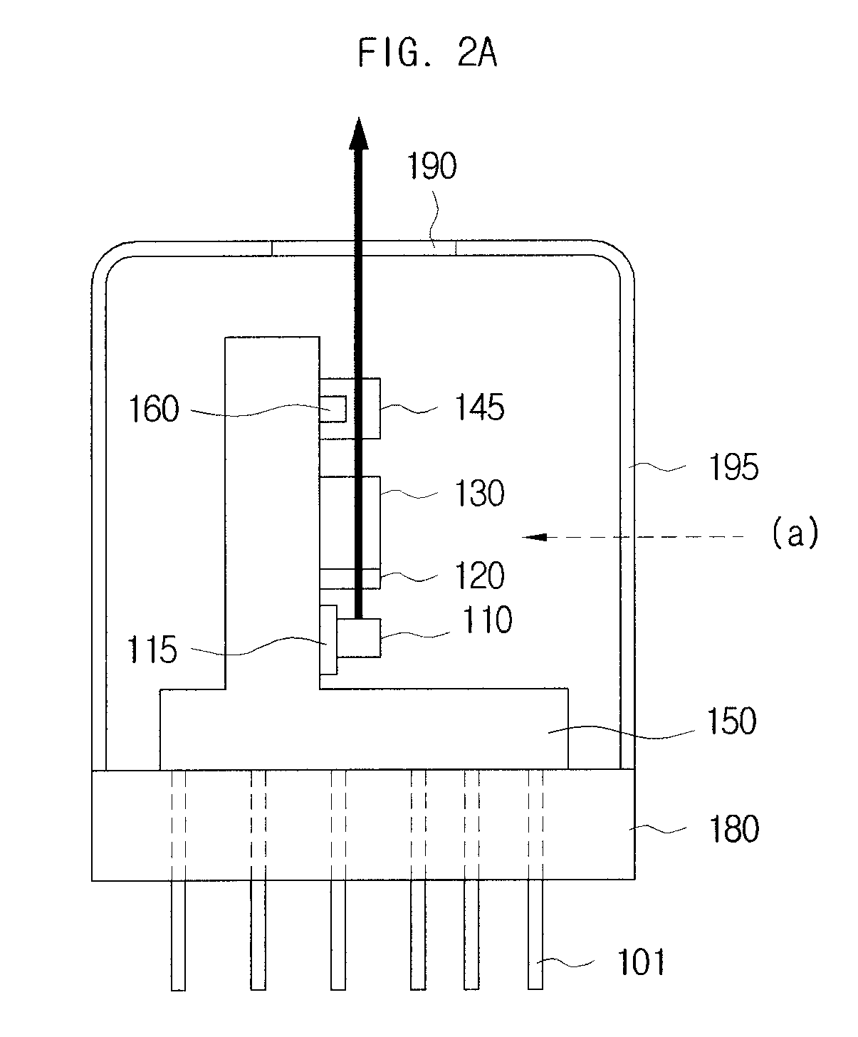
[0108]As shown in FIG. 7, the green laser module package in accordance with the present invention can include the pumping light source 110, a thermoelectric element 115, the laser medium 120 and the optical crystal 130.

[0109]Here, the thermoelectric element 115 can be placed inside the green laser module package and control the operation temperature of the pumping light source 110 to be maintained as a predetermined target temperature by being thermally coupled to the pumping light source 110. In other words, the thermoelectric element 115 of FIG. 7 can function to replace the micro heater 111 described with reference to FIG. 4 and FIG. 5.

[0110]As a result, the thermoelectric element 115 can maintain the operation temperature of the pumping light source 110 as the target temperature determined as the highest temperature by keeping the thermoelectric element 115 in a heating mode instead of a cooling mode. For example, the thermoelectric element 115 can heat the pumping light source ...

fourth embodiment

[0114]However, the same principle described with reference to FIG. 4 and FIG. 5 can be applied to the description with reference to FIG. 7. Also, in accordance with the present invention, the green laser module package can allow the operation temperatures of the laser medium 120 and the optical crystal 130 to be controlled together with the pumping light source 110.

[0115]At this time, the description with reference to FIG. 8 assumes that the pumping light source 110, the laser medium 120 and the optical crystal 130 are placed together on one thermoelectric element 115, separately equipped elements can control the operation temperatures of each or combinations of the pumping light source 110, the laser medium 120 and the optical crystal 130.

[0116]Even though the above description is mainly related to the green laser module package described with reference to FIG. 3 thorough FIG. 7, it shall be easily understood by any person of ordinary skill in the art that the same principle of the...


PUM


Abstract

Disclosed are a laser module apparatus and a display apparatus using the same. In accordance with an embodiment of the present invention, a laser module package which generates a green laser beam can include a pumping light source, configured to generate and output a pump beam; a laser medium, configured to receive the pump beam and output an infrared beam; an optical crystal, configured to receive the infrared beam and output a laser beam having a green wavelength band; and a micro heater, configured to be thermally coupled to the pumping light source and control an operation temperature of the pumping light source to be maintained to a predetermined target temperature.

Description

CROSS-REFERENCE TO RELATED PATENT APPLICATIONS[0001]This application claims the benefit of Korean Patent Application No. 10-2007-0106019, filed on Oct. 22, 2007, in the Korean Intellectual Property Office, the disclosure of which is incorporated herein in its entirety by reference.BACKGROUND OF THE INVENTION[0002]1. Field of the Invention[0003]The present invention relates to a laser module package, more specifically to a laser module package and a display apparatus using the same that can control an operation temperature of a laser diode to be regular by mounting a micro heater or a thermoelectric element in the package.[0004]2. Background Art[0005]Today's development of a color display technology has brought about the gradually increased demand of small-sized display apparatuses such as personal digital assistants (PDA) and portable multimedia player (PMP) as well as big-sized display apparatus such as TV and monitors. In order to form a color image, those apparatuses can use eith...

Claims


Application Information

Patent Timeline
Patent Type & Authority Applications(United States)
IPC IPC(8): H01S3/10H01S3/04
CPCH01S3/025H01S3/042H01S3/09415H01S3/1022H01S3/1611H01S5/06804H01S3/1673H01S5/02296H01S5/02415H01S5/02438H01S5/02453H01S3/1643H01S5/02257G02F1/13
Inventor PARK, HEUNG-WOO
Owner SAMSUNG ELECTRO MECHANICS CO LTD
Learn More