Heat Exchanger System Comprising Fluid Circulation Zones Which are Selectively Coated with a Chemical Reaction Catalyst

a heat exchanger and fluid circulation technology, applied in the field of micro heat exchangers, can solve the problems of increasing the risk of nitrogen oxide formation within the first fluid circulation zone, choosing suitable materials, and often expensive, and achieves the effect of reducing the risk of nitrogen oxide formation, and reducing the risk of forming nitrogen oxides

Inactive Publication Date: 2009-04-23
COMMISSARIAT A LENERGIE ATOMIQUE ET AUX ENERGIES ALTERNATIVES +2
View PDF6 Cites 20 Cited by
  • Summary
  • Abstract
  • Description
  • Claims
  • Application Information

AI Technical Summary

Benefits of technology

[0016]Consequently, the selective distribution of the catalyst in basic channels which are distributed in rows spaced apart on the plate generally makes it possible to obtain a considerable surface homogeneity of the temperature of this plate, which is intended to be the site of an endothermic or exothermic catalytic reaction. Compared to those encountered in the prior art, the basic channels provided in the present invention are present in greater number and are shorter in length, so that it is possible to achieve a better distribution of the hot / cold spots on the plate. Effectively, with the geometry specific to the present invention, the inlets of the basic channels can themselves be distributed homogeneously over the entire face of the plate in question, and are no longer all confined close to one end of the plate as was previously the case. Furthermore, since the number of channels is increased and the quantity of fuel is the same, the hot / cold spots observed at the inlet of these basic channels are not only better distributed but also exhibit more acceptable temperatures.
[0017]In addition, the shorter the length of the basic channels, the more the effects of axial conduction in the plates make it possible to limit the hot / cold spots.
[0018]Finally, in this solution in which the catalytic reaction takes place exclusively in the basic channels and not in the other parts of the fluid circulation zones such as the spaces between rows, the short length of the basic channels makes it possible to substantially minimise the pressure losses, thereby allowing a reduction in size of the peripheral devices which are intended to equip the heat exchanger system, such as pumps, compressors, etc.

Problems solved by technology

Since the catalytic combustion reaction observed in the burner plates takes place very quickly, especially in the presence of hydrogen, it therefore inevitably takes place largely at the inlet of the different parallel channels.
This has the major disadvantage of causing the presence of hot spots in this upstream part of the burner, which has the consequence not only of preventing surface homogeneity of the temperature on the burner plates but also of greatly increasing the risk of formation of nitrogen oxides within the first fluid circulation zones.
Furthermore, it is obvious that the appearance of these hot spots causes extremely high thermal stresses on the plates, so that it is necessary to choose suitable materials, which are often expensive.
On the other hand, certain other parts of the steam reforming plates may conversely not have a sufficiently high temperature to allow the steam reforming reaction, due to the lack of uniformity in the supply of energy provided by the catalytic combustion reaction.
Finally, the hot spots are also harmful to the catalyst, since they are likely on the one hand to impair the attachment of the catalytic layer to the walls and on the other hand to irreversibly degrade the catalytic activity of this same layer.
However, this solution does not appear satisfactory due to the increased complexity of the air injection system and / or fuel injection system that it requires.
However, heat balances have shown that this solution leads to a much higher fuel consumption in the burner, and consequently to a drastic drop in yield of the associated steam reforming system.

Method used


Image

  • Heat Exchanger System Comprising Fluid Circulation Zones Which are Selectively Coated with a Chemical Reaction Catalyst
  • Heat Exchanger System Comprising Fluid Circulation Zones Which are Selectively Coated with a Chemical Reaction Catalyst
  • Heat Exchanger System Comprising Fluid Circulation Zones Which are Selectively Coated with a Chemical Reaction Catalyst

Examples


Embodiment Construction

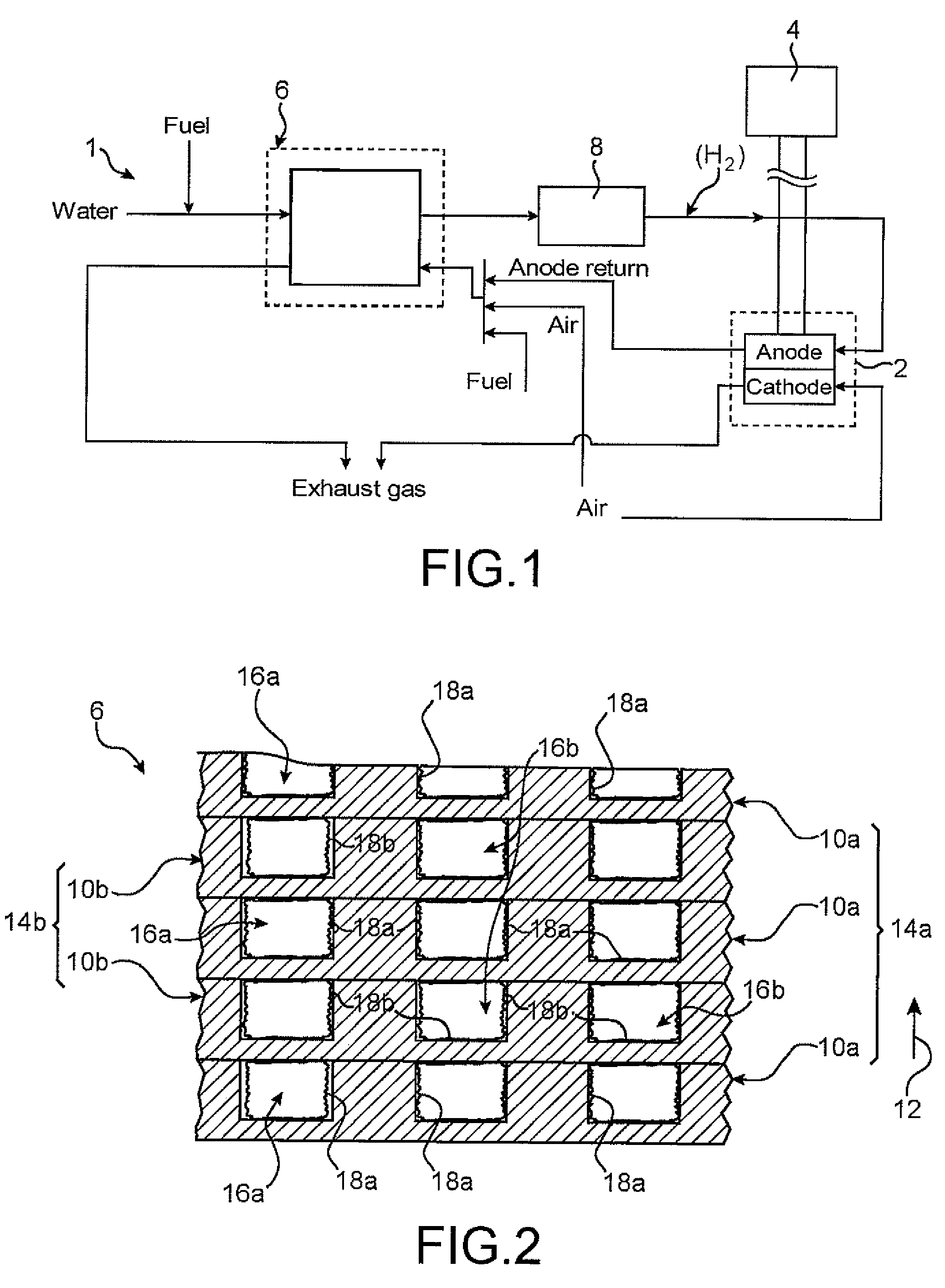
[0052]With reference first to FIG. 1, there can be seen a fuel cell installation 1 according to a preferred embodiment of the present invention.

[0053]This installation 1 therefore incorporates a fuel cell 2, for example of the PEMFC (“Proton Exchange Membrane Fuel Cell”) type, comprising a proton exchange membrane as electrolyte. In a manner known to the person skilled in the art, a fuel cell is an assembly comprising generally a plurality of basic cells stacked one above the other. In each of the basic cells of the fuel cell, an electrochemical reaction takes place between two reagents which are introduced continuously into the basic cells. The fuel (hydrogen) is brought into contact with the anode, while the oxidant (oxygen) is brought into contact with the cathode, the latter being separated from the anode via the electrolyte of the ion exchange membrane type.

[0054]At the anode, an oxidation reaction of the fuel takes place, represented by the following reaction scheme:

2H2→4H++4e...


PUM

PropertyMeasurementUnit
widthaaaaaaaaaa
widthaaaaaaaaaa
temperatureaaaaaaaaaa

Abstract

The invention relates to a plate (10a) intended to be integrated in a stack of plates in a heat exchanger system, the plate comprising a plurality of channels (38) distributed in rows (40), each row comprising side walls (42) arranged opposite one another and spaced apart from one another in a first direction (44), so that two directly consecutive side walls delimit one of the channels (38), the rows being arranged opposite one another and spaced apart from one another in a second direction (46) which is perpendicular to the first. Furthermore, in the fluid circulation zone (20) of the plate incorporating the channels (38), only the latter are coated with a catalyst allowing a chemical reaction.

Description

TECHNICAL FIELD[0001]The invention relates in general to the field of heat exchangers, and preferably to the field of micro heat exchangers in which the heat exchanges obtained are very good due to the high ratio between the heat exchange surfaces and the volume of the heat exchanger.[0002]The invention relates more specifically to heat exchanger systems comprising a stack of plates which alternately form, in a direction of stacking of the plates, a first fluid circulation zone and a second fluid circulation zone, and designed such that a catalytic chemical reaction takes place in at least one of these fluid circulation zones. Therefore, on account of the catalytic chemical reaction which takes place within at least one of these zones, such micro heat exchangers are also known as micro-reactors.[0003]It is noted that many applications are envisaged for the heat exchanger according to the present invention. By way of illustrative example, such a heat exchanger system may take the for...

Claims


Application Information

Patent Timeline
Patent Type & Authority Applications(United States)
IPC IPC(8): H01M8/06B01J19/24C01B3/38
CPCB01J19/0093Y02E60/50B01J2219/00783B01J2219/00822B01J2219/00835B01J2219/00873B01J2219/2453B01J2219/2458B01J2219/2459B01J2219/2462B01J2219/2465B01J2219/2479B01J2219/2485C01B3/384C01B2203/0233C01B2203/066C01B2203/0816C01B2203/0822C01B2203/0827F28D9/0037F28F3/048F28F2260/02H01M8/0618B01J19/249Y02P20/10
Inventor GRUSS, JEAN-ANTOINEDUVAL-BRUNEL, EMMANUELLEVAN VEEN, ANDREMIRODATOS, CLAUDE
Owner COMMISSARIAT A LENERGIE ATOMIQUE ET AUX ENERGIES ALTERNATIVES
Why Eureka
Try Eureka