Endovascular graft for providing a seal with vasculature

a vasculature and endovascular technology, applied in the field of medical devices, can solve the problems of increasing the risk of rupture and hemorrhagic death, the most life-threatening of aneurysms, and the risk of direct surgical intervention of this magnitude, so as to enhance the sealing effect, prevent leakage, and enhance the sealing effect

Inactive Publication Date: 2009-04-23
LIFEPORT SCI
View PDF55 Cites 35 Cited by
  • Summary
  • Abstract
  • Description
  • Claims
  • Application Information

AI Technical Summary

Benefits of technology

[0013]According to one embodiment of the present invention, a sealing member manufactured from a generally flexible fabric and having a frusto-conical shape is connected to an exterior wall of the tubular member of the graft. The sealing member is supported by a biasing member which may be formed from a generally undulating wire frame configured to provide the frusto-conical profile of the sealing member and to impart an outward bias sufficient to compress the sealing member against the vasculature. The sealing member advantageously provides the graft with the ability to expand to assume the shape of the vasculature at the target site, thereby preventing fluid flow into the region between the graft and the vascular wall.
[0014]In a second embodiment of the invention, the graft is configured with a sealing member that is adapted to cooperate with the outward expansion of an attachment system of the graft so that, upon deployment of the graft, the sealing member is moved from a first position remote from the attachment system to a second position overlapping the attachment system. In the deployed state, the sealing member of this embodiment cooperates with fluid flow to enhance the seal between tubular member and vascular wall. Additionally, tufted yarn possibly impregnated with thrombogenic material may be attached to the sealing member, thereby further enhancing the sealing effect.
[0015]In a third embodiment, the improved graft is adapted with a sealing member that has a flexible disk configuration. In this embodiment, a generally undulating biasing member provides the sealing member with an outward bias. The outward bias of the wire frame causes the sealing member to be pressed against the wall of the vessel, substantially preventing leakage between sealing member and vascular wall.
[0016]In a fourth embodiment, there is provided a disk-shaped sealing member, an outer circular edge of which is configured with a wire hoop biasing member. The wire hoop biasing member is packed into a delivery capsule by folding the hoop into a generally zig-zag shape. When deployed from the delivery capsule, the wire hoop unfolds into a circular profile to thereby substantially prevent leakage between sealing member and vascular wall.

Problems solved by technology

One of the most common, and among the most life threatening, is an aneurysm of the abdominal aorta between the renal and iliac arteries.
If untreated, the aneurysm dilates progressively with an ever increasing risk of rupture and hemorrhagic death.
The risks involved in direct surgical intervention of this magnitude are great, and include an extensive recovery period.
However, the use of generally cylindrical grafts to reinforce vascular walls in a patient is not without problems.
One of the challenges encountered with the use of a flexible graft is that, because a diseased vessel is often irregularly shaped, the ends of the graft, even when urged outwardly by an attachment system, may not have a continuous circumferential edge pressed firmly against the inner wall of the vessel.
As a result, fluid may leak into or out of (through a branch vessel) the region between the graft and the vascular wall, thereby increasing fluid pressure on the weakened walls of the vessel and reducing the protective effect of the graft.
The same problem will occur if, as a result of an error in pre-operative sizing of the diseased vessel, a graft is provided that has a diameter slightly smaller than the diameter of the diseased vessel.
Moreover, in the event the target vessel changes shape over time (i.e., increase in neck diameter or shrinkage in aneurysm), perigraft flow may occur.
It will be appreciated that in these situations, because the fabric from which grafts are conventionally made is not circumferentially expandable, a complete seal around the circumference of the vessel will likely not be achieved.

Method used


Image

  • Endovascular graft for providing a seal with vasculature
  • Endovascular graft for providing a seal with vasculature
  • Endovascular graft for providing a seal with vasculature

Examples


Embodiment Construction

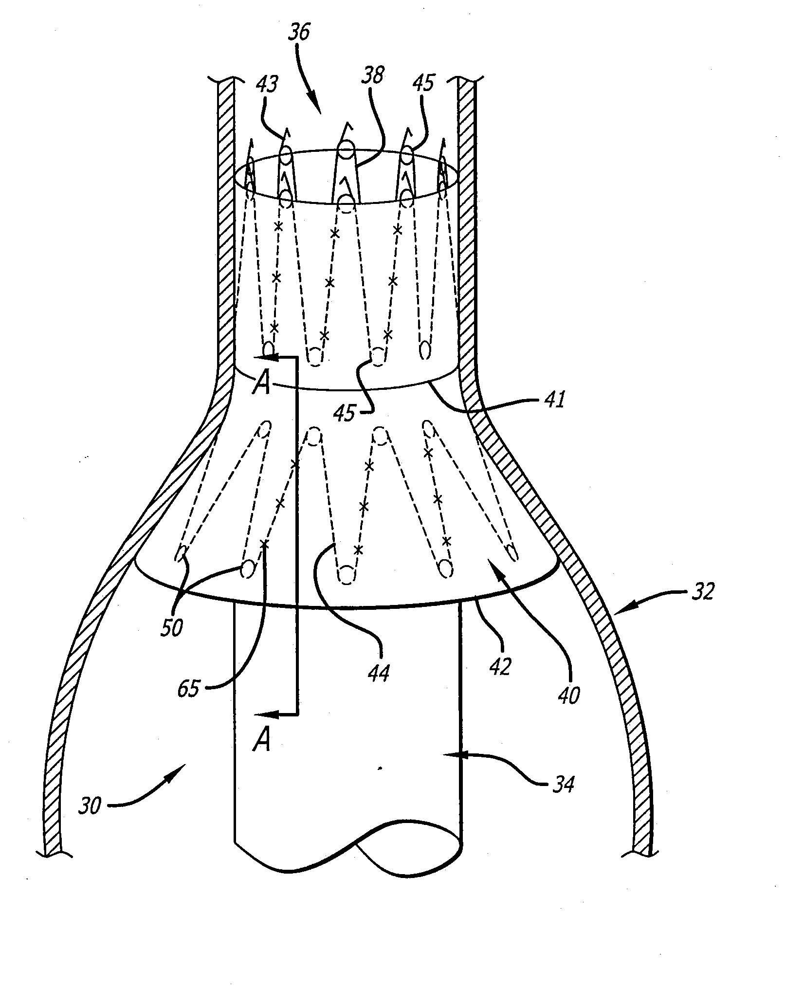
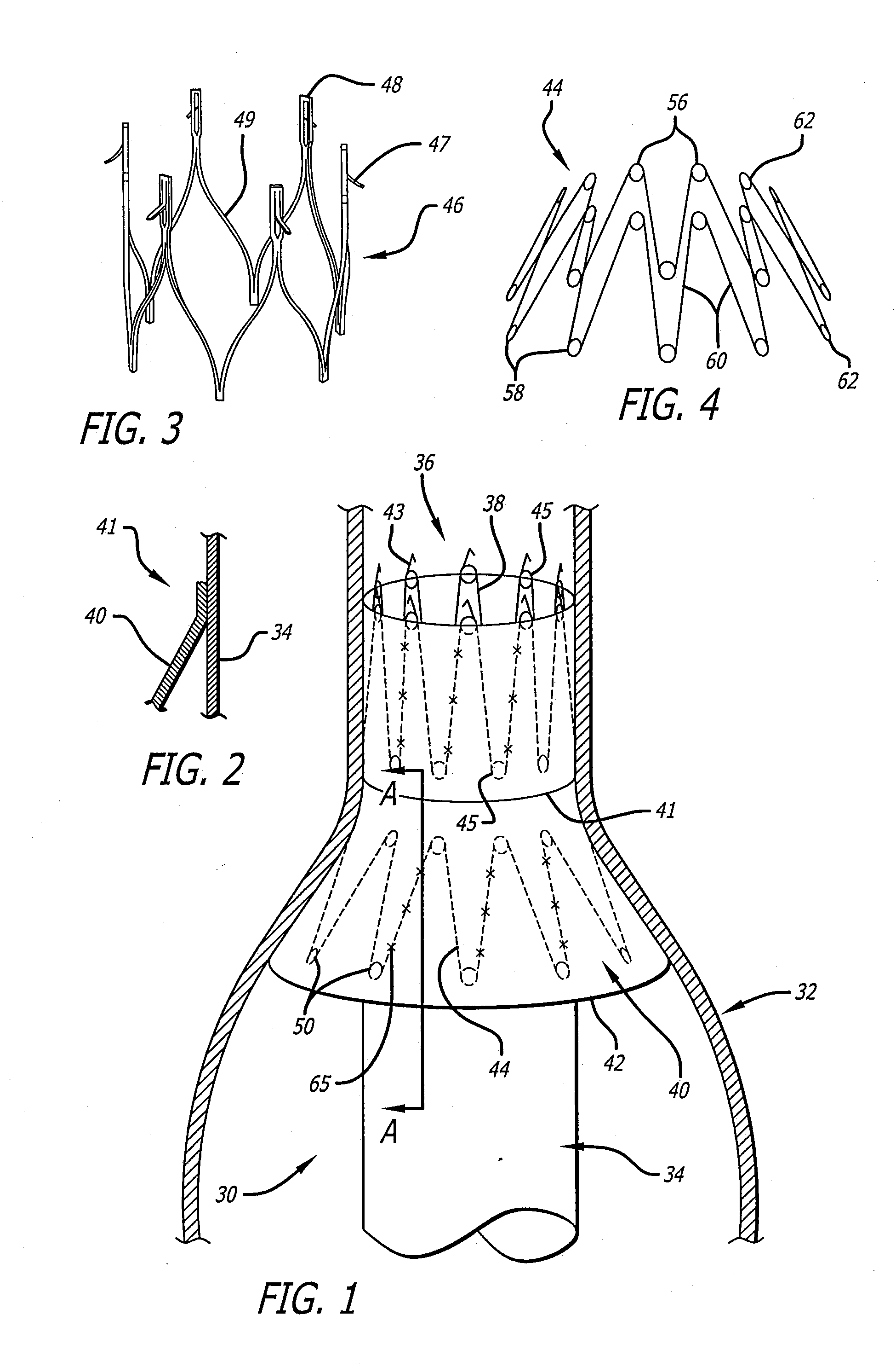
[0044]In general, the present invention involves configuring a graft with a sealing member that operates to occupy spaces between the graft and a lumen into which the graft is implanted. The preferred embodiments of the improved graft are described below. Although the descriptions set forth below generally relate to configuring a proximal end of a graft with a sealing member, the improvement may be applied to the distal end of a graft as well. Where the graft is bifurcated, the disclosed sealing members may be applied to any or all of the ends of such a graft. The term “proximal” as used herein shall mean upstream, while “distal” shall mean downstream.

[0045]FIG. 1 exemplifies a proximal end portion of one embodiment of a graft 30 of the present invention positioned within a vessel 32 of a patient. The vessel 32 is shown to expand from a relatively narrow diameter healthy section to a dilated section where the tissue is diseased. The improved graft 30 comprises a tubular member 34 ha...


PUM


Abstract

A graft provided with a flexible sealing member to substantially prevent blood from leaking between the graft a lumen into which the graft is placed. In one embodiment, the flexible sealing member may be pressed against the vascular wall by an outwardly biased spring means attached to the sealing member. In other embodiments, the sealing member may be self-positioning upon deployment of the graft. The sealing member also may be formed into the shape of a toroid, which may be filled with thrombogenic material causing blood permeating into the toroid-shaped space to coagulate therein and hold the sealing member in place. It is also contemplated that the sealing member be formed from tufts of frayed yarn protruding circumferentially from the outer surface of the graft. A method of manufacturing such tufted yarn sealing members is also disclosed.

Description

CROSS-REFERENCE TO RELATED APPLICATIONS[0001]The present application is a divisional application of U.S. patent application Ser. No. 10 / 796,543, filed on Mar. 8, 2004, which is a divisional application of U.S. patent application Ser. No. 09 / 559,681, filed on Apr. 27, 2000 (now U.S. Pat. No. 6,729,356, which issued on May 4, 2004).BACKGROUND OF THE INVENTION[0002]The present invention relates generally to medical devices, and more particularly to methods and apparatus for the endoluminal placement of tubular prostheses, such as grafts, for repairing aneurysms or other vascular defects in humans and animals.[0003]Aneurysms are discrete dilations of the arterial wall, caused by weakening of the arterial wall. One of the most common, and among the most life threatening, is an aneurysm of the abdominal aorta between the renal and iliac arteries. If untreated, the aneurysm dilates progressively with an ever increasing risk of rupture and hemorrhagic death.[0004]One method of treatment is ...

Claims


Application Information

Patent Timeline
Patent Type & Authority Applications(United States)
IPC IPC(8): A61F2/06A61B17/12A61F2/02D03D3/02D03D3/08D03D27/00
CPCA61B17/12022A61F2230/0067A61B17/12136A61B17/1219A61B2017/1205A61F2/07A61F2/848A61F2002/075A61F2002/077A61F2250/0003D03D3/02D03D3/08D03D27/00Y10S623/921A61F2/89A61B17/12118
Inventor BAKER, STEVEN G.TRAYER, TAMARA L.ESCANO, ARNOLD M.LEMERE, MARKMCDERMOTT, ELIZABETH A.
Owner LIFEPORT SCI
Why Eureka
Try Eureka