
Control system for automotive vehicle having diagnosis function

a technology of control system and automotive vehicle, which is applied in the direction of electric control, machines/engines, instruments, etc., to achieve the effect of easy and rapid detection

Inactive Publication Date: 2009-04-23
DENSO CORP
View PDF10 Cites 13 Cited by
  • Summary
  • Abstract
  • Description
  • Claims
  • Application Information

AI Technical Summary

Benefits of technology

[0006]The present invention has been made in view of the above-mentioned problem, and an object of the present invention is to provide an improved on-board control system in which a failed position is specified by its own diagnosis.
[0009]According to the present invention, positions and kinds of failures in the control system are easily and quickly detected. The means for generating diagnosis information may be simply added to existing circuits to manufacture the control system including the diagnosis function cost-effectively. Other objects and features of the present invention will become more readily apparent from a better understanding of the preferred embodiment described below with reference to the following drawings.

Problems solved by technology

However, this system includes a problem that a particular position in the circuit block having a failure cannot be specified although the circuit block including a failure is specified.

Method used


Image

  • Control system for automotive vehicle having diagnosis function
  • Control system for automotive vehicle having diagnosis function
  • Control system for automotive vehicle having diagnosis function

Examples


Embodiment Construction

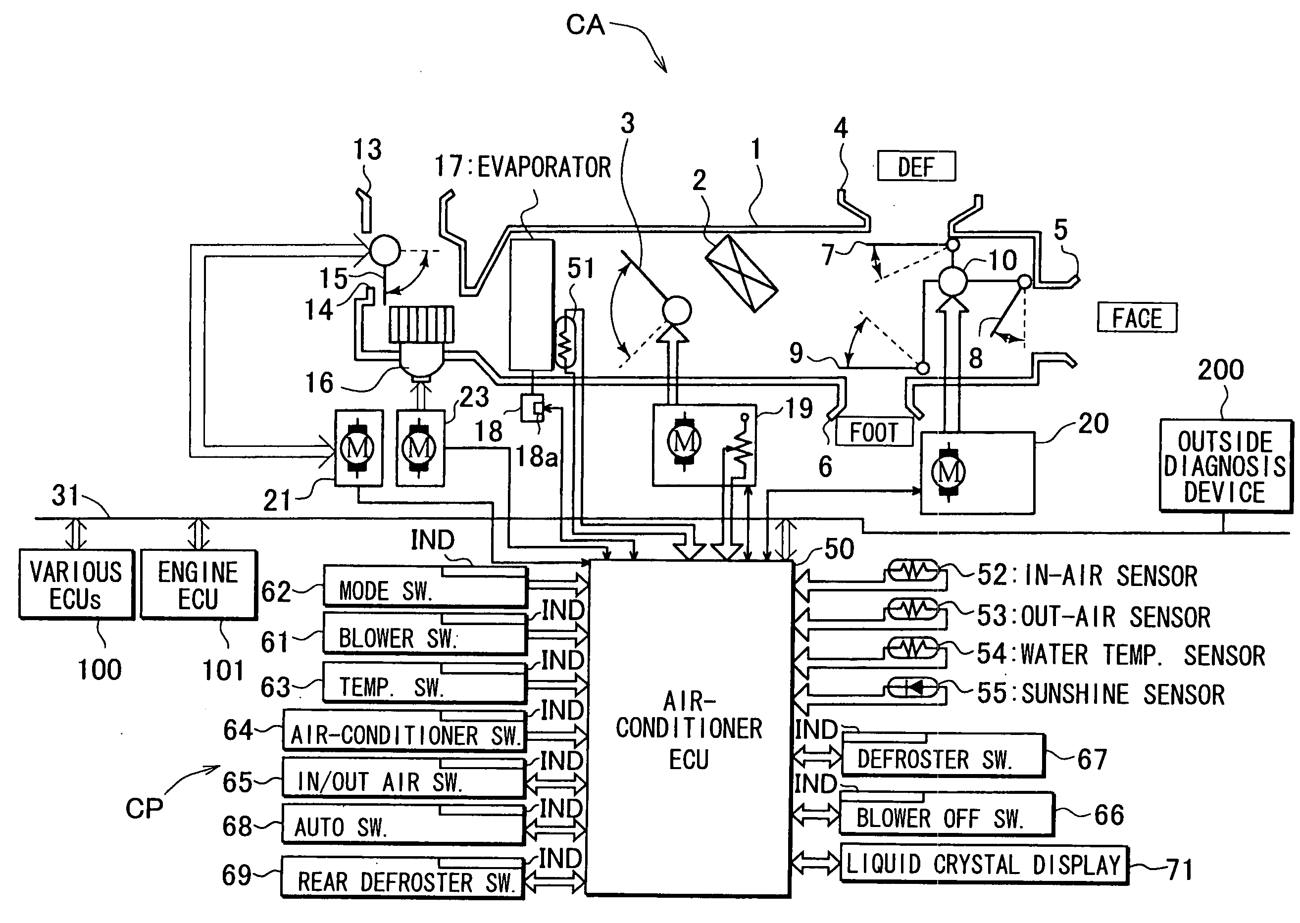
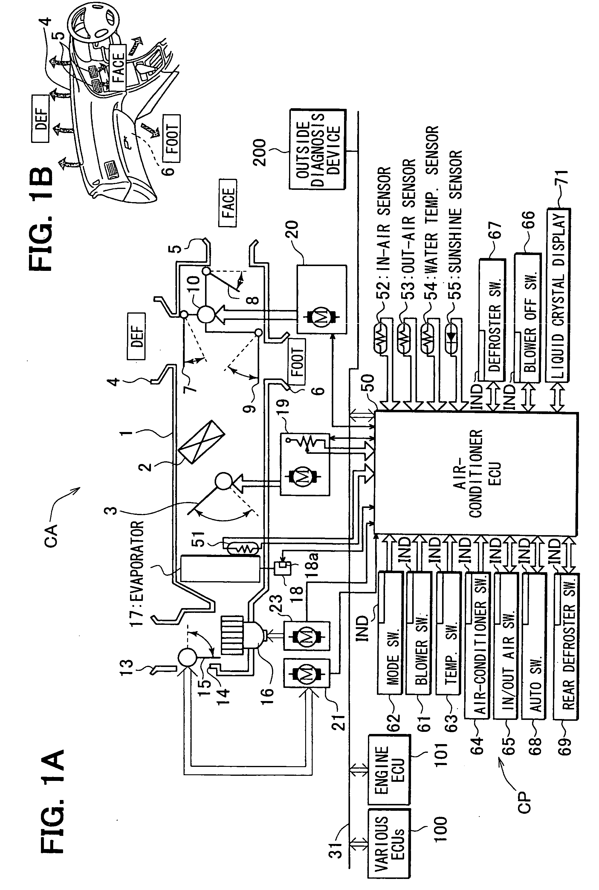
[0015]A preferred embodiment of the present invention will be described with reference to accompanying drawings. FIGS. 1A and 1B show an entire structure of an air-conditioner system CA (as a representative control system for an automotive vehicle) to which the present invention is applied. The air-conditioner CA includes a duct 1 that has an inlet port 13 for introducing in-air (air in a passenger compartment) and an inlet port 14 for introducing out-air (outside air). Introduction of the in-air and the out-air is switched by an in / out switching damper 15, and the in-air or the out-air is introduced into the duct 1 by a blower 16 driven by a blower motor 23.

[0016]In the duct 1, an evaporator 17 for cooling the introduced air and a heater core 2 for heating the air are disposed. An amount of heated air and the cooled air is controlled by an air-mix damper 3. Angular positions of the air-mix damper 3 are controlled by a servomotor 19. The heated air and the cooled air mixed with the ...


PUM


Abstract

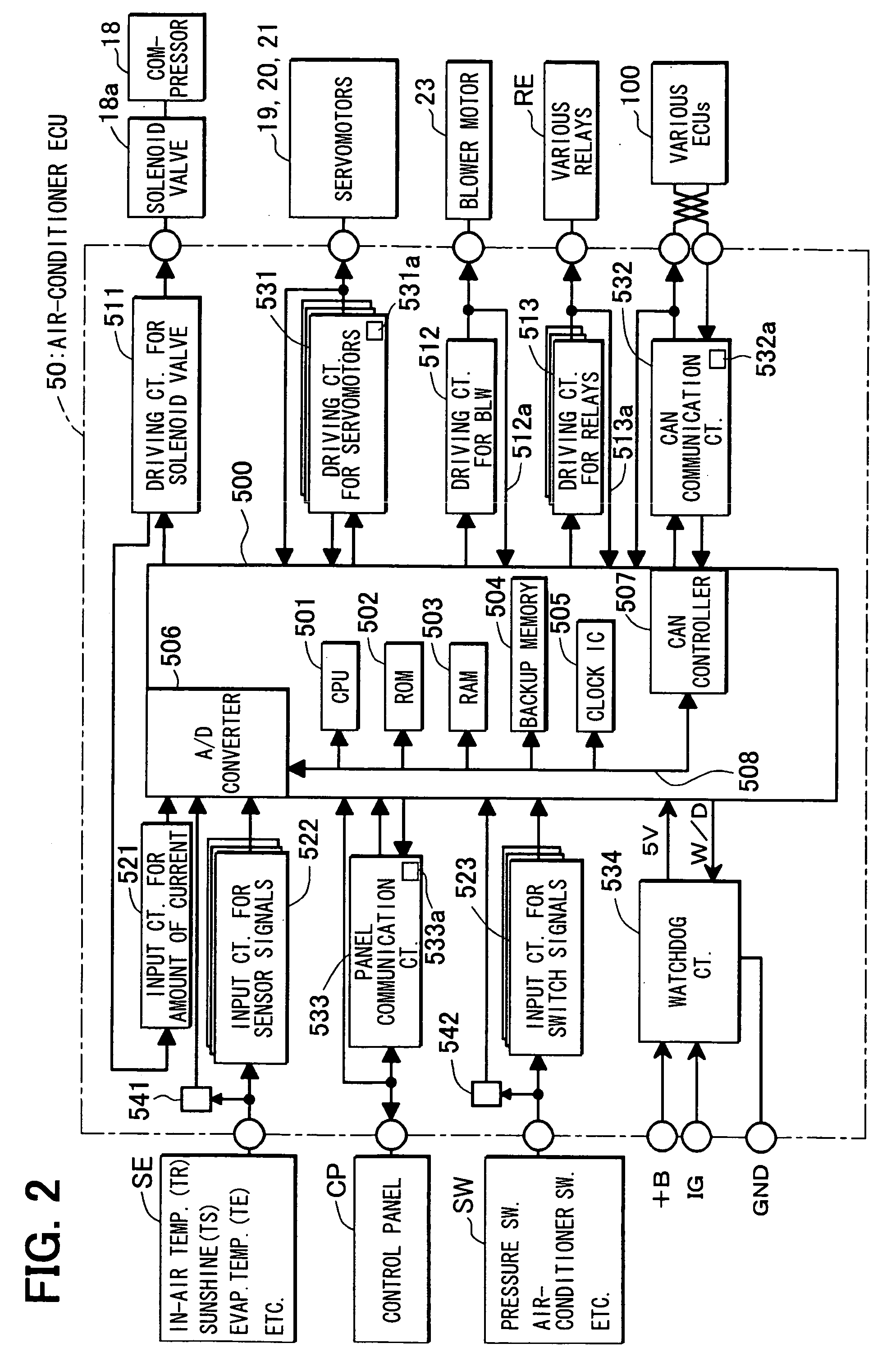
A system for controlling on-board air-conditioner according to the present invention includes input / output means such as sensors and driving motors, a control means such as a microcomputer, and input / output circuits connecting the input / output means to the control means. Means for generating diagnosis information, such as failure flag-setting circuits, feedback circuits and current sensors detecting sensor signals, are included in the input / output circuits. Upon receiving a request for diagnosis from an outside diagnosis device, diagnosis data including positions and nature of the failures occurred in the control system are outputted, taking into consideration the diagnosis information generated and stored in the control means. The diagnosis data may be displayed on a display panel of the outside diagnosis device. The diagnosis information generating means may be simply added to existing input / output circuits to thereby constitute cost-effectively the control system having a diagnosis function.

Description

CROSS-REFERENCE TO RELATED APPLICATION[0001]This application is based upon and claims benefit of priority of Japanese Patent Application No. 2007-249464 filed on Sep. 26, 2007, the content of which is incorporated herein by reference.BACKGROUND OF THE INVENTION[0002]1. Field of the Invention[0003]The present invention relates to a control system for an automotive vehicle, which is able to output diagnosis data for the own system according to a request for diagnosis from an off-board device.[0004]2. Description of Related Art[0005]An example of a control system (an air-bag control system) having a diagnosis function is disclosed in JP-A-2005-63054. The air-bag control system includes an application specific integrated circuit (ASIC) that performs diagnosis of functions necessary for the air-bag control. The diagnosis is performed at a predetermined interval or according to a trigger from outside factors. A microcomputer determines whether a failure or failures occurred in the ASIC ba...

Claims


Application Information

Patent Timeline
IPC IPC(8): F02D45/00
CPCB60H1/00978
Inventor ARAI, HIDENORI
Owner DENSO CORP
Learn More