
Diesel Engine Aftertreatment Control Operation with Waste Heat Recovery

a technology of aftertreatment control and waste heat recovery, which is applied in the direction of machine/engine, exhaust treatment electric control, separation process, etc., can solve the problems of affecting the operation affecting the efficiency of the heater, so as to reduce the potential of self-regeneration and reduce the effect of particulate matter

Inactive Publication Date: 2009-04-30
FORD GLOBAL TECH LLC
View PDF11 Cites 15 Cited by
  • Summary
  • Abstract
  • Description
  • Claims
  • Application Information

AI Technical Summary

Benefits of technology

The patent text describes a system for improving the effectiveness of a diesel particulate filter in an exhaust after treatment system for a lean-burn internal combustion engine. The system includes a heat transfer device, a heater, a filter, and an exhaust path. The heat transfer device isolates the exhaust path from the external surface of the filter to prevent excessive heat transfer. This system allows for recycling of waste heat from the regeneration process without directly subjecting the particulate filter to the thermal load of the heated exhaust gases, reducing the potential for self-sustained regeneration and degradation of the filter. The system also allows for low-temperature combustion processes that generate less particulate matter, reducing the risk of over-temperature and the need for smaller particulate filters.

Problems solved by technology

On the other hand, the particulate filter can be damaged at excessive temperatures.
For example, catalyst particles incorporated into the particulate filter may sinter (reducing the activity of the catalyst), the structural integrity of the filter element may be damaged, etc.
The inventors herein have recognized that these thermal limitations may force a trade-off between the efficiency and reliability of a particulate filter.
Particulate filter devices that attempt to conserve energy by reusing waste heat from the regeneration reaction to directly heat the particulate filter risk potentially self-sustained reactions, especially without a separate cooling mechanism to manage excessive temperatures.
Alternatively, particulate filter devices that do not recycle waste heat from the regeneration reaction may also lower fuel economy, leading to increased operating costs.
Moreover, additional heat shielding and / or cooling may be used if the temperature of the particulate filter effluent is too high to safely pass to downstream devices, adding to manufacturing and / or maintenance costs.
For example, the after treatment system may permit waste heat from the regeneration to be recycled without directly subjecting the particulate filter to the thermal load of the heated exhaust gases exiting the particulate filter, thereby reducing potential of self-sustained regeneration resulting in over-temperature conditions that may degrade the particulate filter or other components.

Method used


Image

  • Diesel Engine Aftertreatment Control Operation with Waste Heat Recovery
  • Diesel Engine Aftertreatment Control Operation with Waste Heat Recovery
  • Diesel Engine Aftertreatment Control Operation with Waste Heat Recovery

Examples


Embodiment Construction

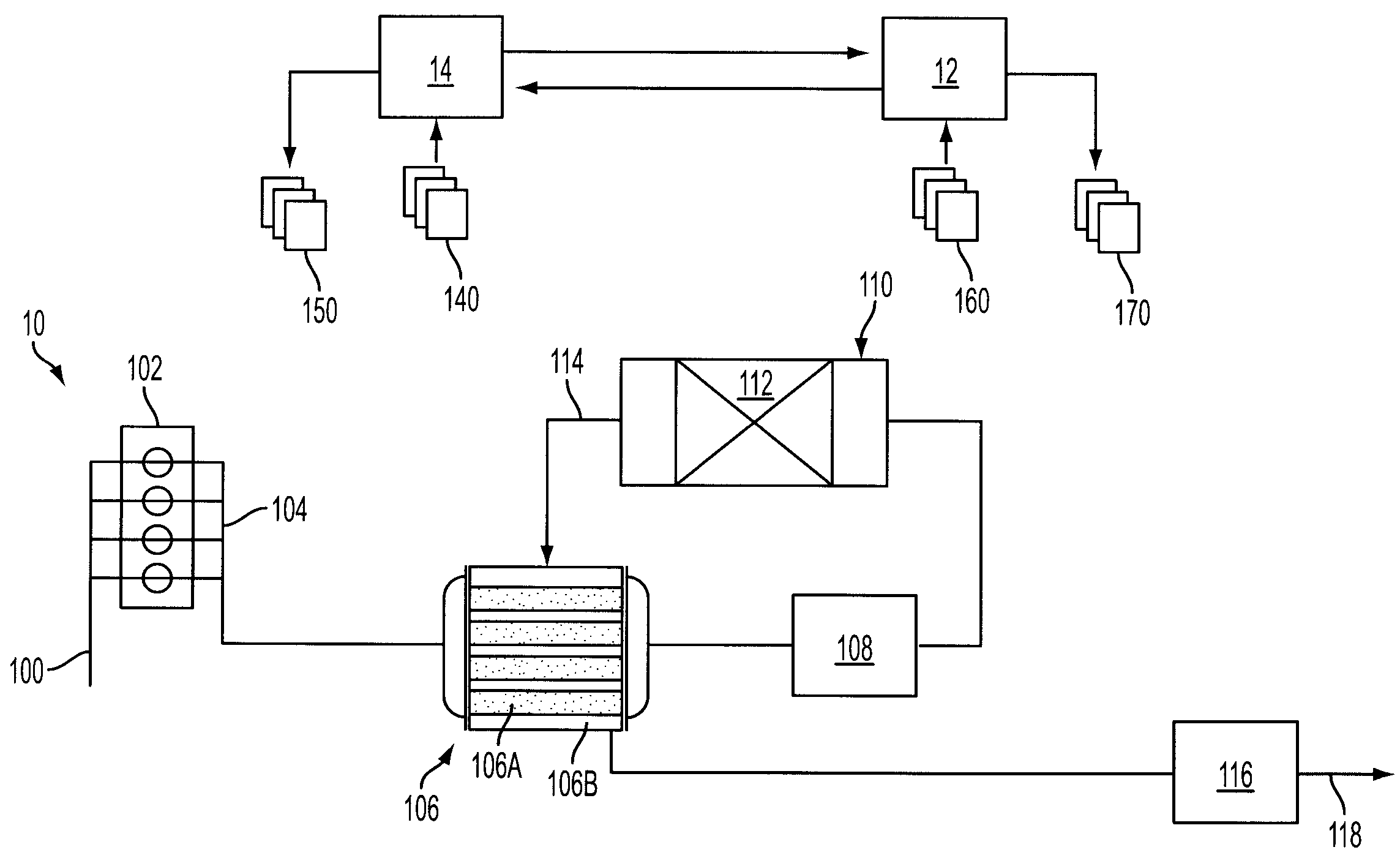
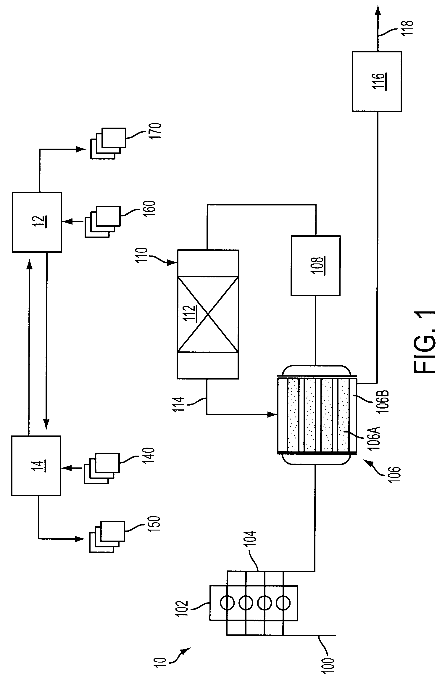
[0007]Referring to FIG. 1, engine 10 may include an intake manifold 100 which may be fluidly coupled to a bank of combustion cylinders 102. Combustion cylinders 102 may communicate with an exhaust manifold 104. A heat transfer device 106 may be coupled to exhaust manifold 104. Heat transfer device 106 may comprise at least two sides 106A and 106B, which permit the transfer of heat between gases on each side without commingling the gases. Heat transfer device 106 may be of various kinds. For example, heat transfer device 106 may be a shell-and-tube heat exchanger, a plate heat exchanger, etc., and, while not shown in FIG. 1, heat transfer device 106 may incorporate baffles on one or more sides to facilitate efficient heat transfer.

[0008]A first side 106A of heat transfer device 106 may be coupled to a heater 108 located downstream of first side 106A of heat transfer device 106. Heater 108 may provide heat from an external, fuel-fired flame, from the combustion of fuel injected into t...


PUM

PropertyMeasurementUnit
reaction rateaaaaaaaaaa
temperatureaaaaaaaaaa
pressureaaaaaaaaaa

Abstract

A diesel engine exhaust gas aftertreatment system is described. The system may comprise a heat transfer device comprising a first side and a second side; a heater downstream of the first side of the heat transfer device, a filter downstream of the heater; and, an exhaust path downstream of the filter leading to the second side of the heat transfer device, wherein the exhaust path is isolated from an external surface of the filter to inhibit heat transfer from the heated exhaust gas exiting the filter to the external surface of the filter.

Description

BACKGROUND AND SUMMARY[0001]The effectiveness of a diesel particulate filter (DPF) in an exhaust after treatment system for a lean-burn internal combustion engine can be improved by periodically regenerating the particulate filter. Regeneration typically involves elevating the temperature of the particulate filter, thereby combusting adsorbed particulates. While regeneration is exothermic and may produce enough energy to be self-sustaining after initiation, lean-burn internal combustion engines typically have an exhaust gas temperature that is lower than that required to activate regeneration. Thus, many particulate filter devices incorporate heat sources such as catalysts or heaters to initiate the regeneration process. On the other hand, the particulate filter can be damaged at excessive temperatures. For example, catalyst particles incorporated into the particulate filter may sinter (reducing the activity of the catalyst), the structural integrity of the filter element may be dam...

Claims


Application Information

Patent Timeline
Patent Type & Authority Applications(United States)
IPC IPC(8): F01N3/023F01N3/035
CPCB01D46/4218B01D46/448B01D46/46F01N3/027Y02T10/47F01N2260/08F01N2560/06F01N2560/08F01N2900/0408F01N9/002Y02T10/40F01N3/023
Inventor CHYO, TIMOTHY SUNG JAEKONG, JIANTENNISON, PAUL JOSEPH
Owner FORD GLOBAL TECH LLC
Learn More