In-line stirling energy system

Active Publication Date: 2009-04-30
PENN STATE RES FOUND +1
View PDF19 Cites 3 Cited by
  • Summary
  • Abstract
  • Description
  • Claims
  • Application Information

AI Technical Summary

Benefits of technology

[0006]The present invention involves the provision of the combination of a Stirling engine core in combination with an energy conversion device. A Stirling engine includes an engine core having a pair of heat exchangers preferably in combination with a heat transfer device. There are a plurality of engine cores and a plurality of power conversion devices operably coupled together to provide the Stirling engine

Problems solved by technology

For example, steam generation is usually accomplished in very large, very heavy equipment particularly with regard to the generator and the steam turbine that drives the generator.
Steam generation is typically not portable.
Internal combustion engines likewise, to be efficient, are also very large and are typically diesel powered and are prone to vibrating.
These too are typically not easily portable.
There are portable generators that are small but tend to be relatively inefficient.
Generators using internal combustion engines are typically limited to a single type of fuel such as diesel fuel, gasoline, gasoline / alcohol mixtures, or propane.
Additionally, generator devices typically have a low power output per unit of volume.
While such generating systems are effective for producing electric current, they have their drawbacks, some of which were discussed above.
Problems associated with a piston-style engine is the friction between the pistons and cylinder walls, leakage of gas through the piston-cylinder wall gaps, the presence of moving mechanical parts at high temperature, and the inability to produce multiphase electricity, for example, three phase electricity from the generator without additional equipment to convert single phase to multiphase electricity.
However, to date, attempts at using Stirling engines for the production of electricity have not been successful particularly when it is desired to generate multiphase electric current without conversion.
Another problem with the use of internal combustion engines which can be used in portable generators or fixed generators, is that they have a tendency to vibrate and produce noise, both at the exhaust and in their normal vibrations from moving parts.
While these can be reduced, they require expensive muffler systems and vibration damping systems.
Also, as mentioned above, such engines are fuel specific, mechanically complex, and they have a significant amount of friction associated with their moving components resulting in inefficiencies.

Method used


Image

  • In-line stirling energy system
  • In-line stirling energy system
  • In-line stirling energy system

Examples


Embodiment Construction

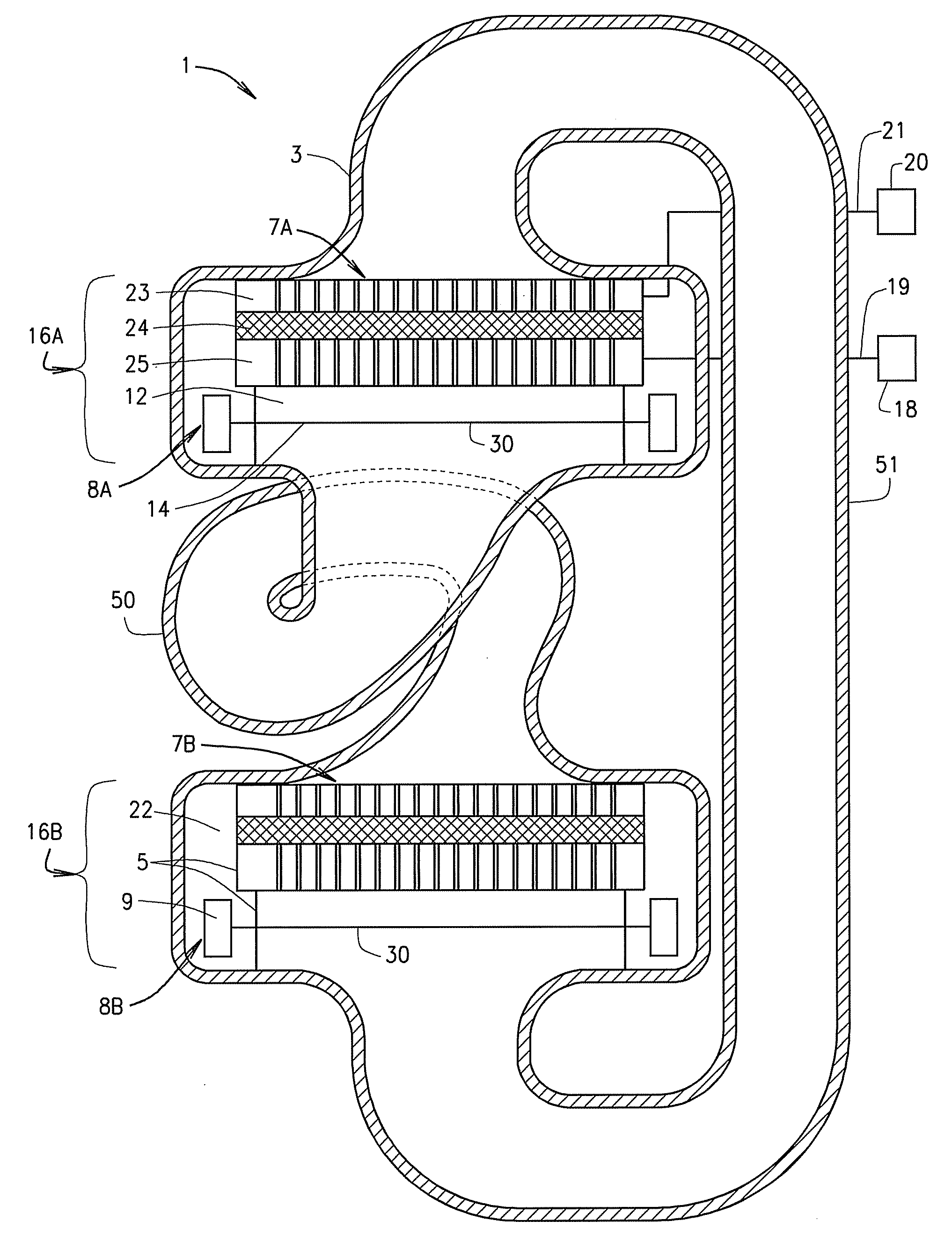
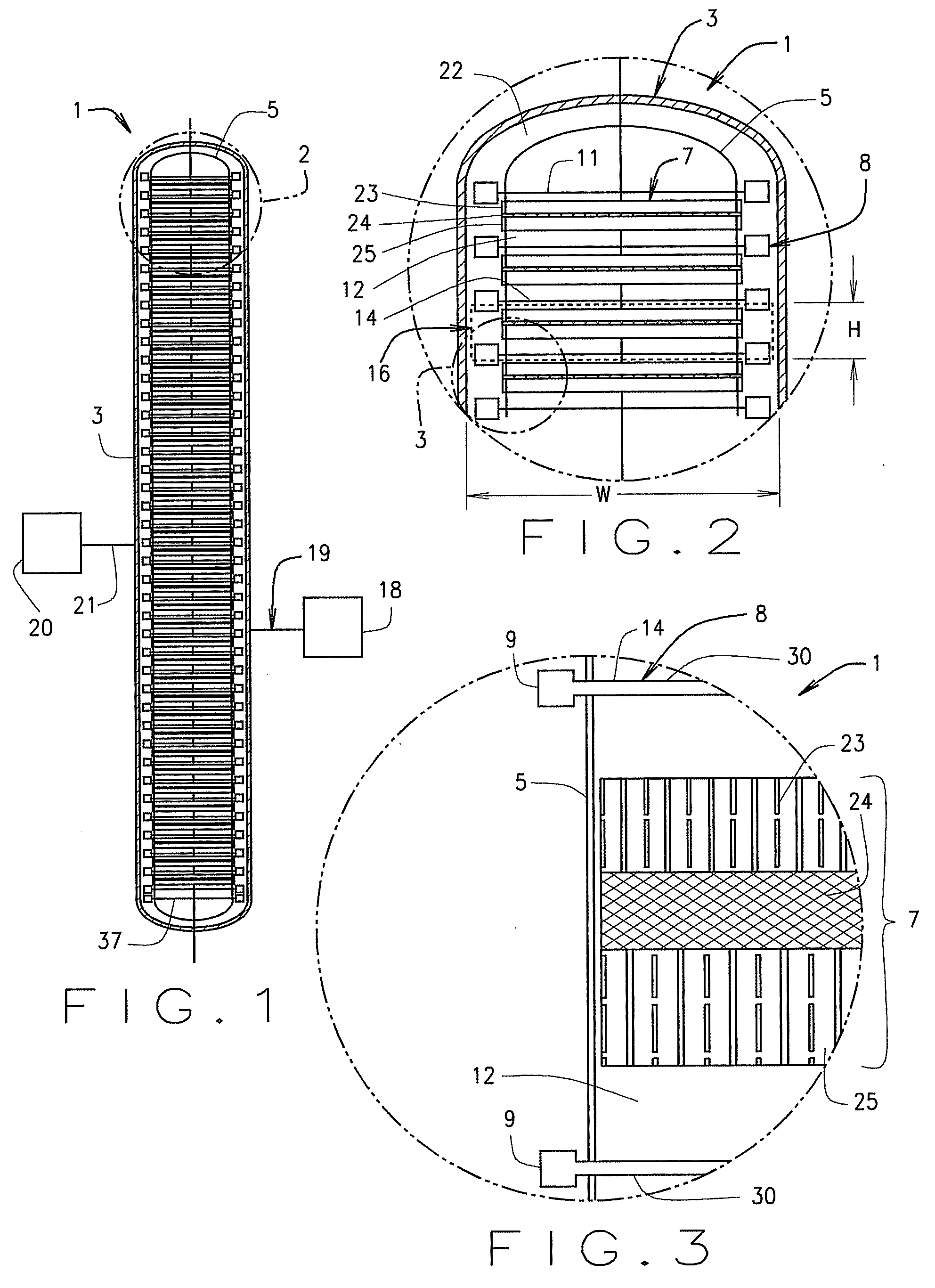
[0021]FIG. 1 illustrates one embodiment of the present invention. The reference numeral 1 designates generally a Stirling engine system comprising an external pressure vessel or housing 3. Inside the pressure vessel 3 is an acoustic shell 5 containing a plurality of Stirling engines each designated generally 7 and coupled to a respective energy conversion device 8 such as an alternator device designated generally 9. A launching or starting device such as a launching compressor 11 is provided which initiates the propagation of an acoustic wave at the desired frequency through the various Stirling engines 7. The Stirling engines 7 preferably operate at a frequency in the range of between about 40 Hz and about 1000 Hz. Each alternator 9 includes a driven element 14. Between each Stirling engine 7 and respective energy conversion device 8 is a thermal zone 12 to thermally isolate, e.g., a work conversion device such as a driven element 14, from a respective Stirling engine 7. An engine ...


PUM


Abstract

A high efficiency generator is provided using a Stirling engine to amplify an acoustic wave by heating the gas in the engine in a forward mode. The engine is coupled to an alternator to convert heat input to the engine into electricity. A plurality of the engines and respective alternators can be coupled to operate in a timed sequence to produce multi-phase electricity without the need for conversion. The engine system may be operated in a reverse mode as a refrigerator / heat pump.

Description

STATEMENT REGARDING FEDERAL RIGHTS[0001]This invention was made with government support under contract number DE-AC52-06NA25396 and cooperative agreement DE-FC26-04NT42113 awarded by the U.S. Department of Energy, and grant N00014-03-1-0652 awarded by the U.S. Office of Naval Research. The government has certain rights in the invention.BACKGROUND OF INVENTION[0002]The generation of electrical energy has long been practiced. Generation can be, for example, by coal-fired or nuclear-powered power plants, typically using steam turbines. Hydroelectric generation using dammed up water, large internal combustion engines driving generators, wind generators, photovoltaic electric generation, portable generators and the like are also used. Chemical reactions may also be used to generate electricity or electric current. Each type of generator has its advantages and disadvantages. For example, steam generation is usually accomplished in very large, very heavy equipment particularly with regard ...

Claims


Application Information

Patent Timeline
IPC IPC(8): F01B29/10
CPCF02G1/0435H02K7/1815F02G2243/54
Inventor BACKHAUS, SCOTT N.KEOLIAN, ROBERT
Owner PENN STATE RES FOUND
Why Eureka
Try Eureka