
Chemical treatment system and method

a chemical treatment system and chemical treatment technology, applied in the direction of settling tank feed/discharge, process and machine control, chemical complex/solubilisation treatment, etc., can solve the problems of increased costs and harm to the wastewater treatment system of the plant, prone to operator error and neglect, and loss of treatment with its associated cos

Inactive Publication Date: 2009-04-30
HONEYWELL INT INC
View PDF5 Cites 18 Cited by
  • Summary
  • Abstract
  • Description
  • Claims
  • Application Information

AI Technical Summary

Benefits of technology

The present invention is a chemical treatment system that injects a chemical solution into a process for corrective action of a condition of the process. The system includes a chemical storage system and a chemical treatment management system. The chemical treatment management system receives a notification of the condition and determines the dosage of the chemical solution needed to correct the condition. The system can also receive inputs from other factors such as operating settings, process environmental conditions, production rates, and raw material cost. The chemical treatment system can produce reports on the usage and effectiveness of the chemical solution, and can also alert operators of pitting or high corrosion events. The system can also be controlled by wireless communication and can provide recommendations for corrective actions based on environmental factors and available inventory of chemicals. The chemical treatment system can also include multiple chemical storage tanks for different chemical solutions for treating different conditions of the process.

Problems solved by technology

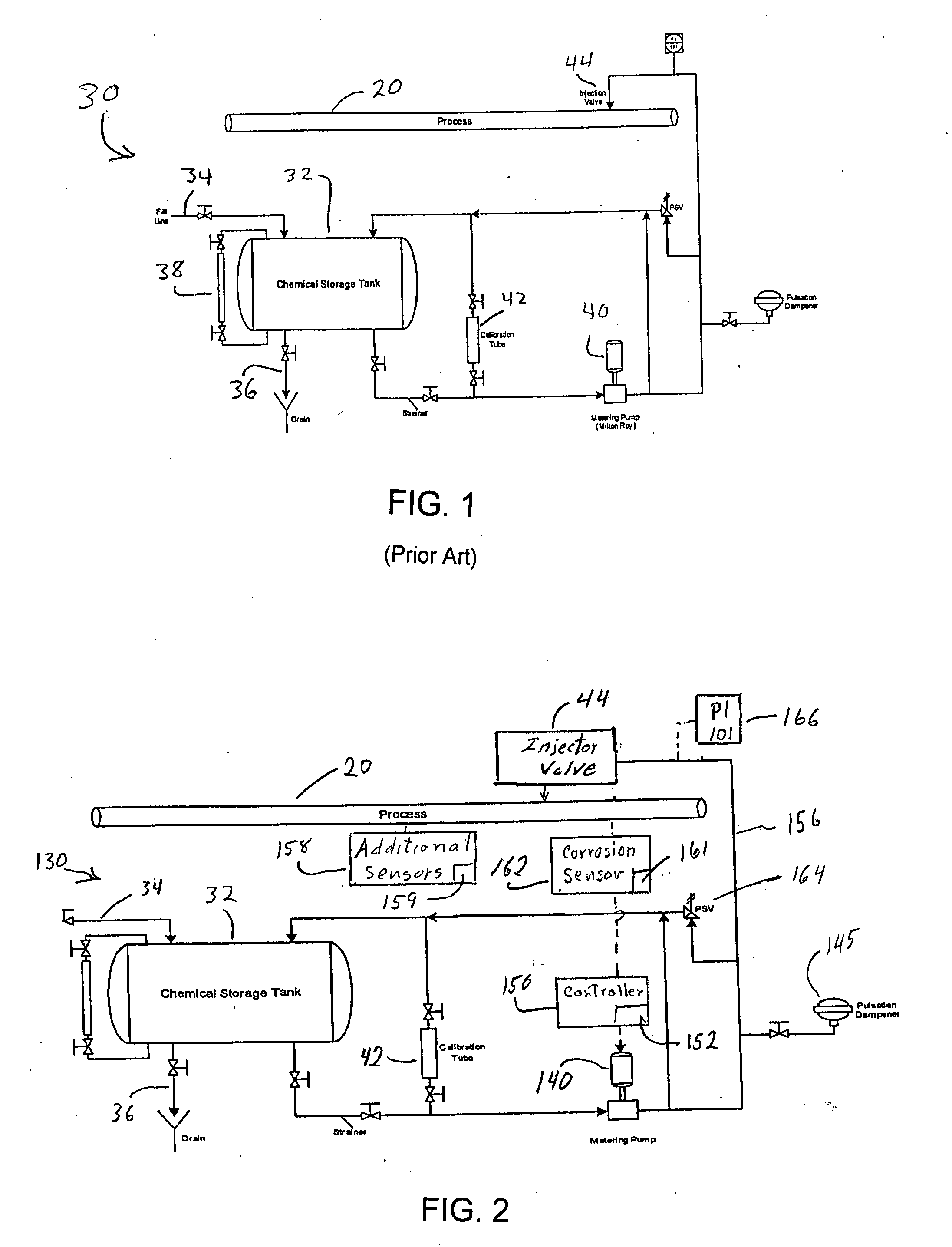
System 30 is operated almost entirely manually making it prone to operator error and neglect.
All of these incidents resulted in additional costs and harm to the plant's wastewater treatment system.
Low inventory can cause the loss of treatment with its associated cost in terms of increased corrosion, reduced throughput caused by foaming, etc.
Expedited delivery of additional chemicals can add substantially to the cost of chemical treatment.

Method used


Image

  • Chemical treatment system and method
  • Chemical treatment system and method
  • Chemical treatment system and method

Examples


Embodiment Construction

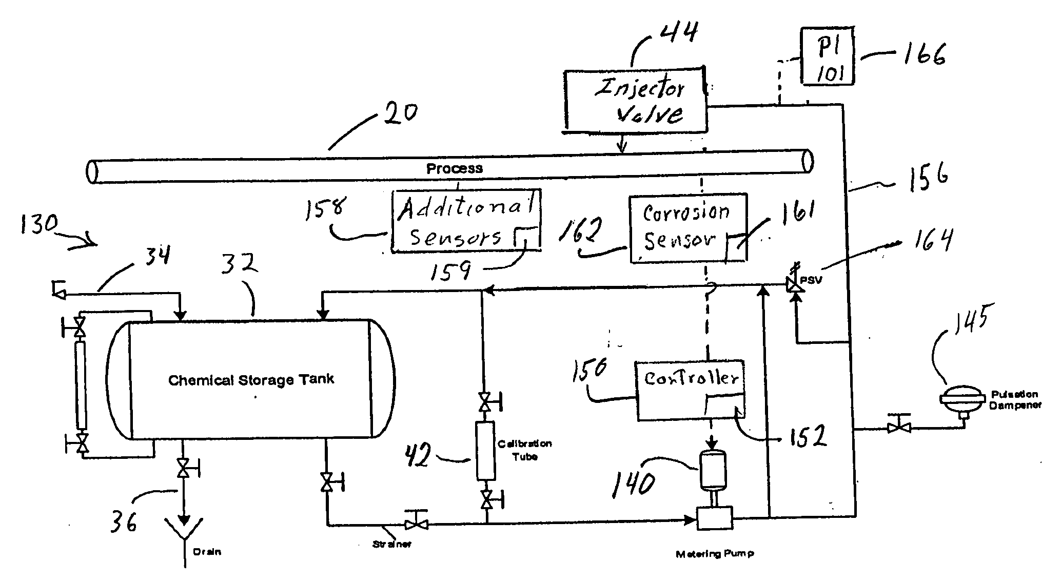
[0043]Referring to FIG. 2, a chemical treatment system 130 is disposed to control chemical treatment of a process 20. Chemical treatment system 130 includes components that are the same as components included in FIG. 1 and that bear like reference numerals.

[0044]Chemical treatment system 130 comprises a vessel, shown as a skid-mounted drum 32 with a fill line 34, a drain line 36, a calibration tube 42 and a sight glass 38 for visual inspection of drum inventory. In a preferred embodiment a corrosion inhibitor is supplied to drum 34 via fill line 34. The corrosion inhibitor may vary from one process to another.

[0045]Chemical treatment system 130 further comprises a corrosion sensor 162 disposed to sense corrosion and / or scaling in process 20 and to supply an output signal that is a function of the corrosion rate. Corrosion sensor 162 may be any suitable corrosion sensor. For example, corrosion sensor 162 may be a SmartCet™ probe, SmartCet™ being a trademark of Honeywell International...


PUM

PropertyMeasurementUnit
chemicalaaaaaaaaaa
corrosionaaaaaaaaaa
pressureaaaaaaaaaa

Abstract

A chemical treatment system that injects one or more dosage chemical solutions into a process. Conditions of the process are sensed by sensors, communicated to a chemical treatment management system. The chemical treatment management system processes the process conditions and issues command signals to one or more chemical storage systems to provide a dosage of chemical to the process. The chemical storage systems each comprise a chemical storage tank, a level sensor for the tank, a controller and a pump. The controller uses the command signals for varying in real time the dosage of the chemical solution by varying the pump operation. The chemical treatment management system also uses additional data from the chemical storage systems, such as tank level, and from other sources to provide the command signals and alerts / alarms and other user information.

Description

RELATED APPLICATION[0001]This application is related to commonly assigned U.S. application Ser. No. ______, filed concurrently herewith, Attorney Docket No. 0011831-103.FIELD OF THE INVENTION[0002]This invention relates to a system and method for chemical treatment of a process.BACKGROUND OF THE INVENTION[0003]Chemical treatment management systems are used in chemical and refinery plants for major operational areas such as process units, cooling water systems, steam generating systems and wastewater systems and other systems. The chemical treatments are used for corrosion and scale control (corrosion and scale inhibiting chemicals), bio-control (biocides and disinfectants), pH control (pH adjusters), foaming control (anti-foaming and defoamers), emulsion control (emulsion breakers), solids control (coagulants and flocculants) and others.[0004]Most chemical treatment systems are small stand-alone systems monitored by outside operators. These systems are often neglected by operators a...

Claims


Application Information

Patent Timeline
Patent Type & Authority Applications(United States)
IPC IPC(8): C02F5/08B01F15/02C23F11/00G05D21/00
CPCC02F1/686C02F5/08C02F2209/005C02F2209/008C02F2209/02C23F11/00C02F2209/04C02F2209/06C02F2209/40C02F2209/42C02F2209/03
Inventor CHEN, YU-GENE T.DINELLO, RON
Owner HONEYWELL INT INC
Learn More