Laser scanning microscope

a scanning microscope and laser technology, applied in the field of microscopes, can solve the problems of detachment of electrodes, degradation of resolution and brightness, and significant problems in specimen preparation using dic and oblique illumination

Inactive Publication Date: 2009-04-30
EVIDENT CORP
View PDF8 Cites 13 Cited by
  • Summary
  • Abstract
  • Description
  • Claims
  • Application Information

AI Technical Summary

Benefits of technology

[0017]An embodiment of the present invention is a laser scanning microscope comprising an infrared pulse laser; an objective lens focusing an infrared light from the infrared pulse laser on a sample; a condenser lens disposed on an opposite side of the objective lens across the sample for collecting an observation light that is generated by a nonlinear optical effect and has a wavelength shorter than a wavelength of the infrared light; a visible light detector detecting the observation light collected by the condenser lens, in which an IR partial transmission filter having partially-modified transmission characteristics with respect to the infrared light is disposed near a front focal position of the condenser lens, and an infrared light detector detecting, through the IR partial transmission filter, a transmitted light from the sample collected by the condenser lens, is provided.
[0018]Another embodiment of the prese...

Problems solved by technology

However, the preparation of a specimen using the DIC and oblique illumination has a significant problem.
However, the laser entering the objective lens is to produce spots while it is spilt by the prism into two light fluxes that are slightly shifted sideways on the sample position, causing the degradation of resolution and decrease in brightness.
However, when carrying out observation using the patch-clamp method, there have been problems such as the slight shake generated by these operations...

Method used


Image

  • Laser scanning microscope
  • Laser scanning microscope
  • Laser scanning microscope

Examples


embodiment 1

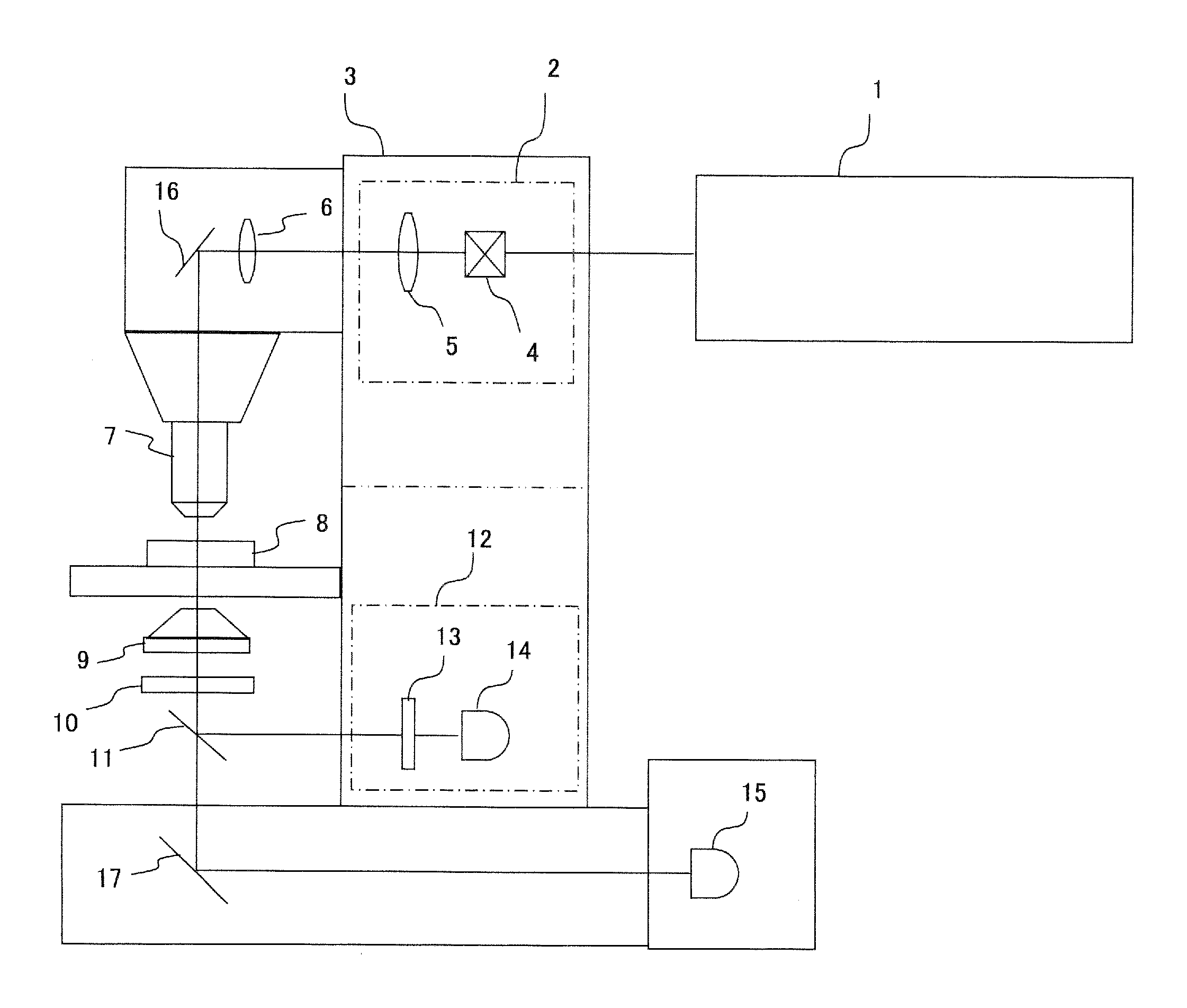
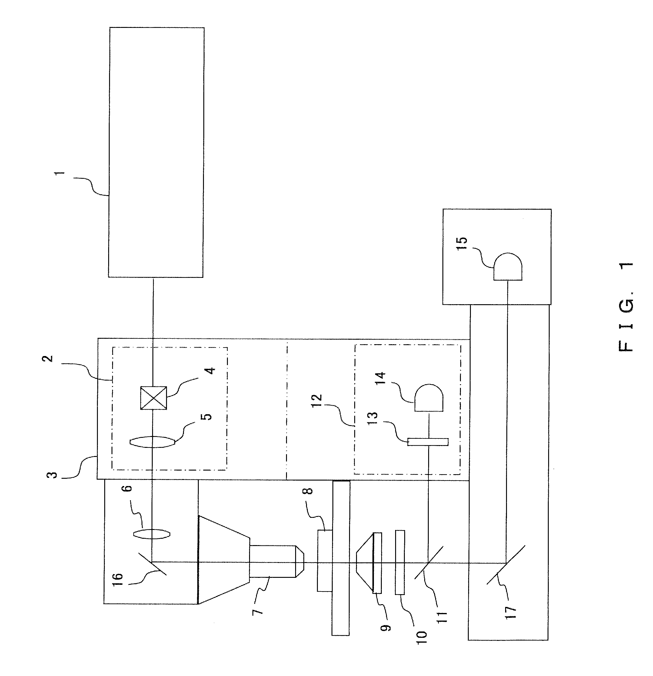
[0025]FIG. 1 is a schematic diagram illustrating an embodiment of a multiphoton-excitation laser scanning microscope according to the present invention. An infrared pulse laser 1 is generally used as the excitation light source in a multiphoton-excitation laser scanning microscope. One reason for using the pulse laser is that the photon density on the focal plane can be effectively increased. Since the infrared pulse laser 1 is a large apparatus, it is disposed outside the microscope, and an infrared light (excitation light) from the infrared pulse laser 1 is directed to the scanning unit 2. The configuration shown in FIG. 1 where the scanning unit 2 is built into the microscope 3 is not a limitation, and the scanning unit 2 may be disposed outside the microscope 3.

[0026]The infrared light emitted from the infrared pulse laser 1 is directed to the scan unit 2, and is deflected by scanning means 4 such as a galvano mirror disposed inside the scanning unit 2. Since the scanning means ...

embodiment 2

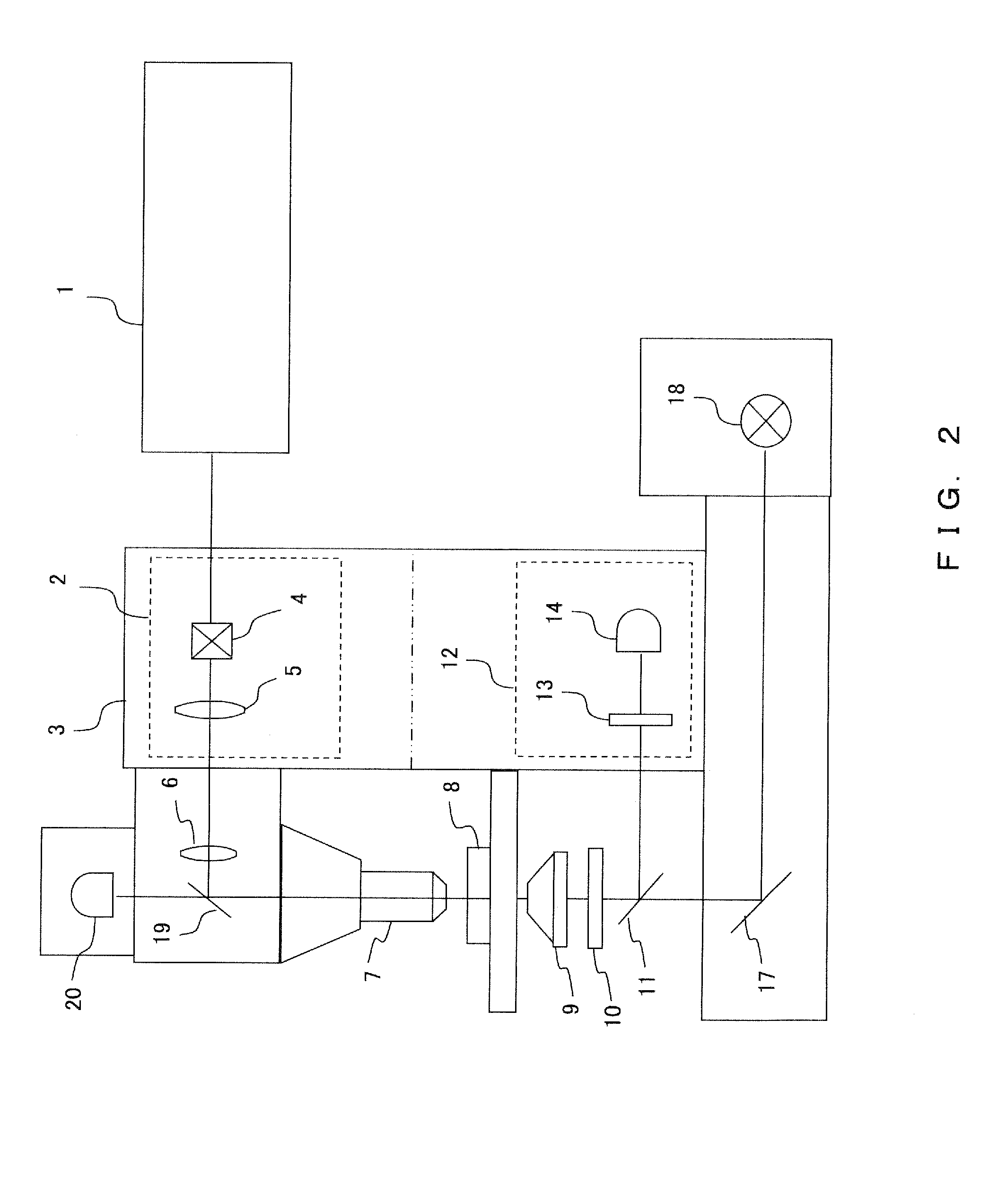
[0035]Hereinafter, the outline of the entire configuration of a multiphoton-excitation laser scanning microscope according to another embodiment is described referring to FIG. 2.

[0036]In the same manner as in Embodiment 1, an infrared pulse laser 1 is generally used as the excitation light source. The infrared light emitted from the infrared pulse laser 1 is directed to a scanning unit 2, passes through scanning means 4, a pupil projection lens 5, an imaging lens 6, and the like, and is irradiated on a sample 8 through an objective lens 7. In this regard, in the same manner as in Embodiment 1, the scanning unit 2 may either be built into the microscope 3 or may be disposed outside.

[0037]In the present embodiment, to detect the transmitted light as well as in Embodiment 1, the fluorescence from the sample 8 is collected by a condenser lens 9. After passing through the condenser lens 9, the fluorescence is passed through an IR partial transmission filter 10 that is disposed on the fro...


PUM


Abstract

In a laser scanning microscope comprising an infrared pulse laser; an objective lens focusing an infrared light from the infrared pulse laser on a sample; a condenser lens disposed on an opposite side of the objective lens across the sample for collecting an observation light that is generated by a nonlinear optical effect and has a wavelength shorter than a wavelength of the infrared light; a visible light detector detecting the observation light collected by the condenser lens, an IR partial transmission filter having partially-modified transmission characteristics for the infrared light is disposed near a front focal position of the condenser lens, and an infrared light detector detecting, through the IR partial transmission filter, a transmitted light from the sample collected by the condenser lens, is provided.

Description

CROSS REFERENCE TO RELATED APPLICATIONS[0001]This application claims benefit of Japanese Application No. 2007-282653, filed Oct. 31, 2007, the contents of which are incorporated by this reference.BACKGROUND OF THE INVENTION[0002]1. Field of the Invention[0003]The present invention relates to the technical field of microscopes.[0004]2. Description of the Related Art[0005]A fluorescence observation method using multiphoton excitation has been known as a method of fluorescence observation with a microscope.[0006]With the multiphoton excitation, a fluorescent material is irradiated with light beams having a wavelength corresponding approximately to the integral multiple of the absorption wavelength simultaneously, inducing an excitation phenomenon that is equivalent to the excitation phenomenon generated by the original absorption wavelength. The multiphoton excitation phenomenon is called a nonlinear phenomenon, which occurs with a rate proportional to the square of the intensity of th...

Claims


Application Information

Patent Timeline
IPC IPC(8): G02B21/06H01J43/04H01J40/14
CPCG02B21/002G02B21/16G02B21/0076G02B21/0032
Inventor YOKOI, EIJI
Owner EVIDENT CORP
Why Eureka
Try Eureka