Turbine System and Method for Extracting Energy From Waves, Wind, and Other Fluid Flows

a turbine system and fluid flow technology, applied in the direction of wind energy generation, machines/engines, wind energy generation, etc., can solve the problems of increasing devices that do not provide for capturing wave potential energy, and are exposed to a limited amount of wave power, so as to reduce manufacturing and operating costs, reduce energy loss, and increase power generation capacity

Inactive Publication Date: 2009-04-30
BORDEN SAXON D
View PDF18 Cites 5 Cited by
  • Summary
  • Abstract
  • Description
  • Claims
  • Application Information

AI Technical Summary

Benefits of technology

[0018]Another object of the invention is to provide a wave turbine that interacts with only a small portion of a wave front at any single moment in time so as not to significantly impede the flow of the wave.
[0021]Another object of the invention is to provide a wave turbine that would minimize energy losses due to reflected waves.
[0024]Another object of the invention is to provide a turbine that minimizes hazards to marine and wild life.SUMMARY OF THE INVENTION
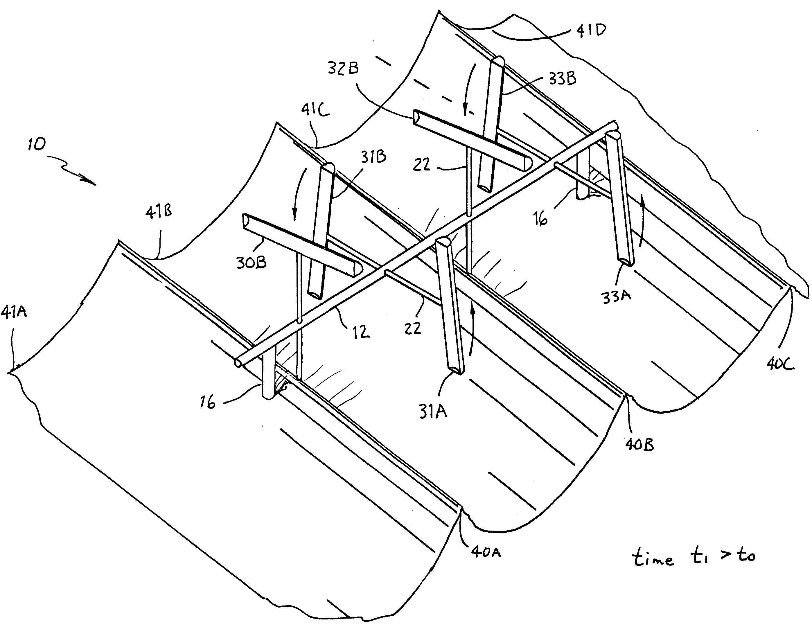
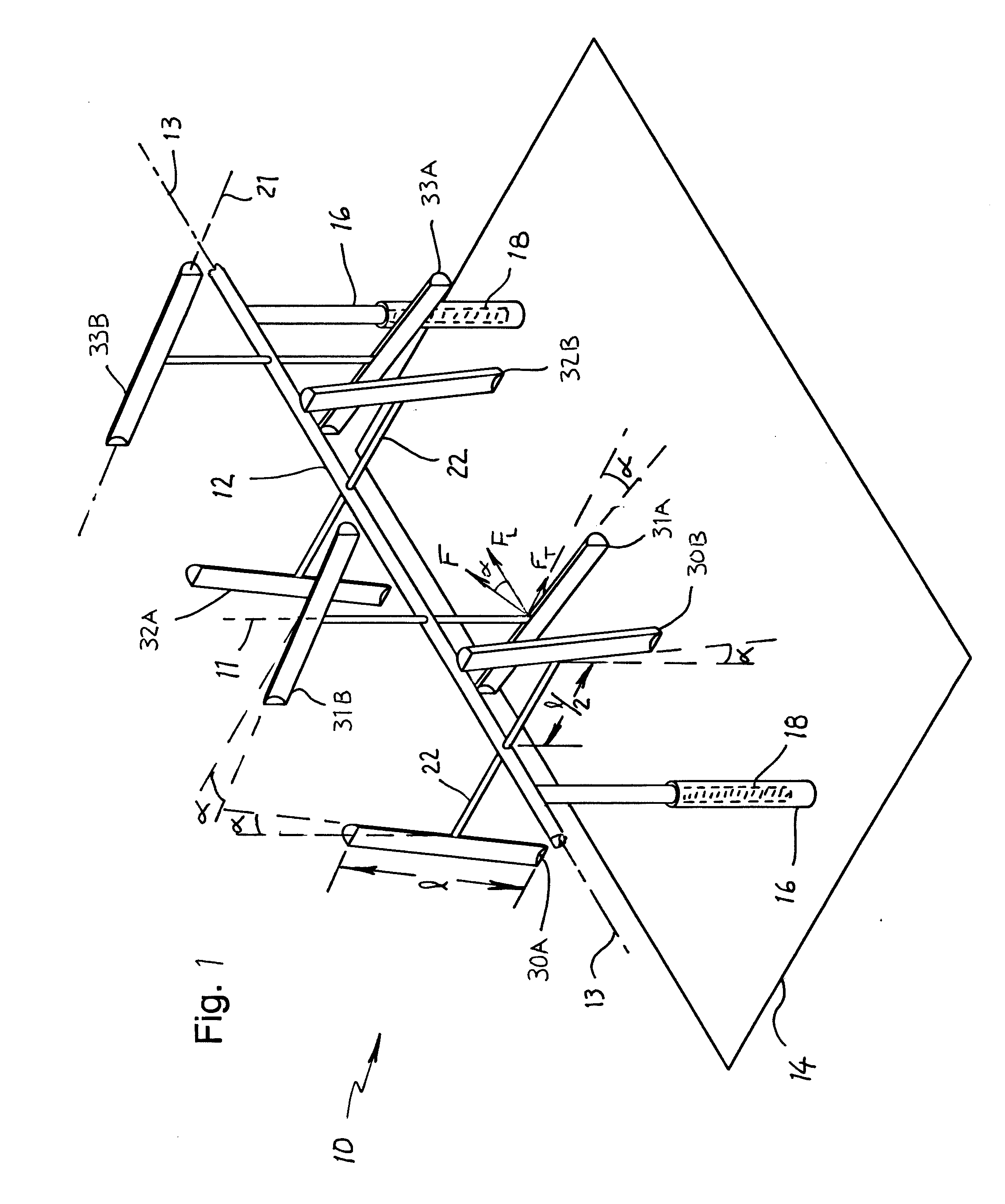
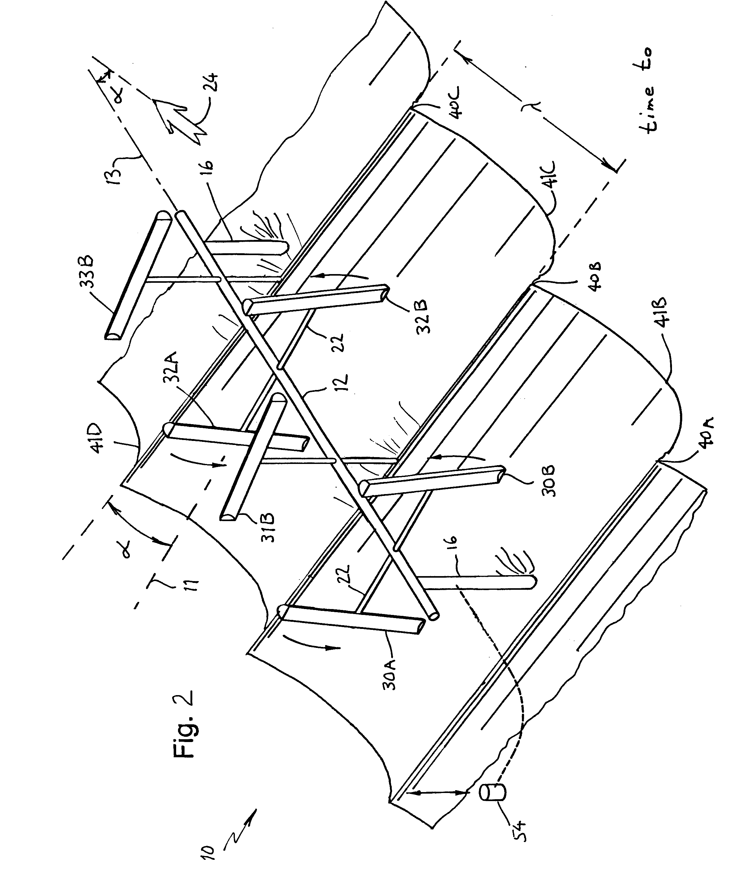
[0027]The long shaft, positioned at an oblique angle (α) to the wave fronts, allows multiple waves to engage the turbine at all times. As a particular wave passes the turbine, only a small portion of that wave impacts a bucket at any given instant. The wave pushes and lifts the lower bucket in a first bucket pair from the 6 o'clock to the 9 o'clock position, rotating the shaft and causing the 3 o'clock bucket in the adjacent second downstream bucket pair to move into the 6 o'clock position. As that wave front progresses, a different portion of the wave pushes and lifts the lower 6 o'clock bucket of the second bucket pair, rotating the shaft and the adjacent downstream third bucket pair into the wave-engaging position, and so on down the line.

Problems solved by technology

The Smith et al. device promotes continuous revolution of the paddlewheel and minimized wave reflections, but the device makes no provision for capturing potential energy of the waves.
U.S. Pat. No. 6,935,832 issued to Platt et al. discloses a turbine device arranged for axial flow; due to its reduced footprint, such an arrangement is only exposed to a limited amount of wave power.
However, the complexity and large number of moving parts in the Haleem device increases its manufacturing and operating costs, particularly in the harsh ocean environment.

Method used


Image

  • Turbine System and Method for Extracting Energy From Waves, Wind, and Other Fluid Flows
  • Turbine System and Method for Extracting Energy From Waves, Wind, and Other Fluid Flows
  • Turbine System and Method for Extracting Energy From Waves, Wind, and Other Fluid Flows

Examples


first embodiment

[0056]FIG. 5 is a cross section view, taken transversely to bucket longitudinal axis 21, of a bucket 30′ of wave turbine 10 according to the invention. Bucket 30′ has an open box-like scoop 60 formed of an arcuate back wall 62 of length l (FIG. 1) sandwiched between two endplates 64. Scoop 60 is designed to extract wave kinetic energy by capturing a portion of the wave therein. Bucket 30′ also includes a drum 66 that is preferably formed of a cylindrical wall 68, also of length l sandwiched between two endplates 70. Drum 66 is watertight, sealed from the ocean environment, and filled with air or foam for positive buoyancy. As bucket 30′ becomes submerged in a wave crest, its positive buoyancy creates an upward lifting force that converts a portion of the wave's potential energy to bucket kinetic energy for rotating the turbine drive shaft. A number of ribs 72 are longitudinally intervaled and connected between scoop 60 and drum 66 for connecting the two members and creating strength...

second embodiment

[0057]FIG. 6 is a cross section view, taken transversely to bucket longitudinal axis 21 along lines 6-6 of FIG. 4, of bucket 31B of wave turbine 10 according to the invention. FIG. 7 is an exploded diagram of FIG. 6. Referring to FIGS. 6-7 collectively, bucket 31B has an open box-like scoop 80 formed of an arcuate double-hull wall 81 of length l (FIG. 1). The double-hull wall 81 is formed of an inner arcuate wall 82, which forms the back wall of scoop 80, and an outer arcuate wall 84. Double-hull wall 81 is sandwiched between two endplates 86. Scoop 80 is designed to extract wave kinetic energy by capturing a portion of the wave therein. Double-hull wall 81 defines a watertight cavity 88, which is sealed from the ocean environment and filled with air or foam for positive buoyancy. As bucket 31B becomes submerged in a wave crest, its positive buoyancy creates an upward lifting force that converts a portion of the wave's potential energy to bucket kinetic energy for rotating the turbi...


PUM


Abstract

An apparatus for harvesting fluid energy including a wave turbine consisting of a long shaft having pairs of buckets positioned at intervals along the shaft and rotated 90 degrees from each adjacent pair. Each bucket is connected at an offset angle with respect to a plane that is normal to the shaft. When adapted for harnessing wave energy, the shaft is elevated above water surface and positioned at an oblique angle to the prevailing wave fronts. Each bucket is positively buoyant, so that buckets capture both potential and kinetic wave energy.

Description

CROSS REFERENCE TO RELATED APPLICATION[0001]This application is based upon provisional application 61 / 000,447 filed on Oct. 26, 2007, the priority of which is claimed.BACKGROUND OF THE INVENTION[0002]1. Field of the Invention[0003]This invention relates generally to a source of alterative and environmentally clean energy, and in particular, to a system and method for extracting energy from ocean waves.[0004]2. Description of the Prior Art[0005]With increasing petroleum prices, political conflict, and the concern of global warming, there exists a growing world demand for alternative energy sources. It has been estimated that the total power of waves breaking on the world's coastlines at any given moment is between 2-3 terawatts. In favorable areas, such as environments typical of the west coast of the United States, Alaska, the north Atlantic coast, Canada, Europe, Australia, Hawaii, South Africa, and Chile, where the wave amplitude may reach 5-10 meters, wave power density may avera...

Claims


Application Information

Patent Timeline
Patent Type & Authority Applications(United States)
IPC IPC(8): F03B13/20
CPCF03B13/1825F03D9/008Y02E10/721Y02E10/38F05B2250/712Y02E10/30Y02E10/72Y10S416/06
Inventor BORDEN, SAXON D.
Owner BORDEN SAXON D
Why Eureka
Try Eureka