
Gas Laser Device

a laser device and laser technology, applied in lasers, laser optical devices, laser construction details, etc., can solve the problems of increasing the cost and overall structural weight of the structure, using additional beam folds, etc., and achieves the effects of reducing cost, lightening weight, and simplifying construction

Active Publication Date: 2009-04-30
LUXINAR LTD
View PDF5 Cites 7 Cited by
  • Summary
  • Abstract
  • Description
  • Claims
  • Application Information

AI Technical Summary

Benefits of technology

[0006]Accordingly, it is the object of one aspect this invention to eliminate the above-described difficulties and draw-backs accompanying the required beam correction of a conventional asymmetric hybrid planar waveguide device. More specifically, an object of an aspect of the present invention is to provide a gas laser vessel operating with a asymmetric hybrid planar waveguide resonator that produces a near diffraction limited round beam that does not require any further external correction. Such a device, in comparison with an asymmetric hybrid planar waveguide laser having a conventional correction system, will be simpler in construction, lower in cost and lighter in weight.

Problems solved by technology

However, in order to achieve the required correction within the limitation of keeping the corrective scheme no longer than the length of the laser discharge vessel, it is often required that additional beam folds be used.
Such designs often require additional frameworks and optical mounting systems, driving up costs and overall structural weight.

Method used


Image

  • Gas Laser Device
  • Gas Laser Device
  • Gas Laser Device

Examples


Embodiment Construction

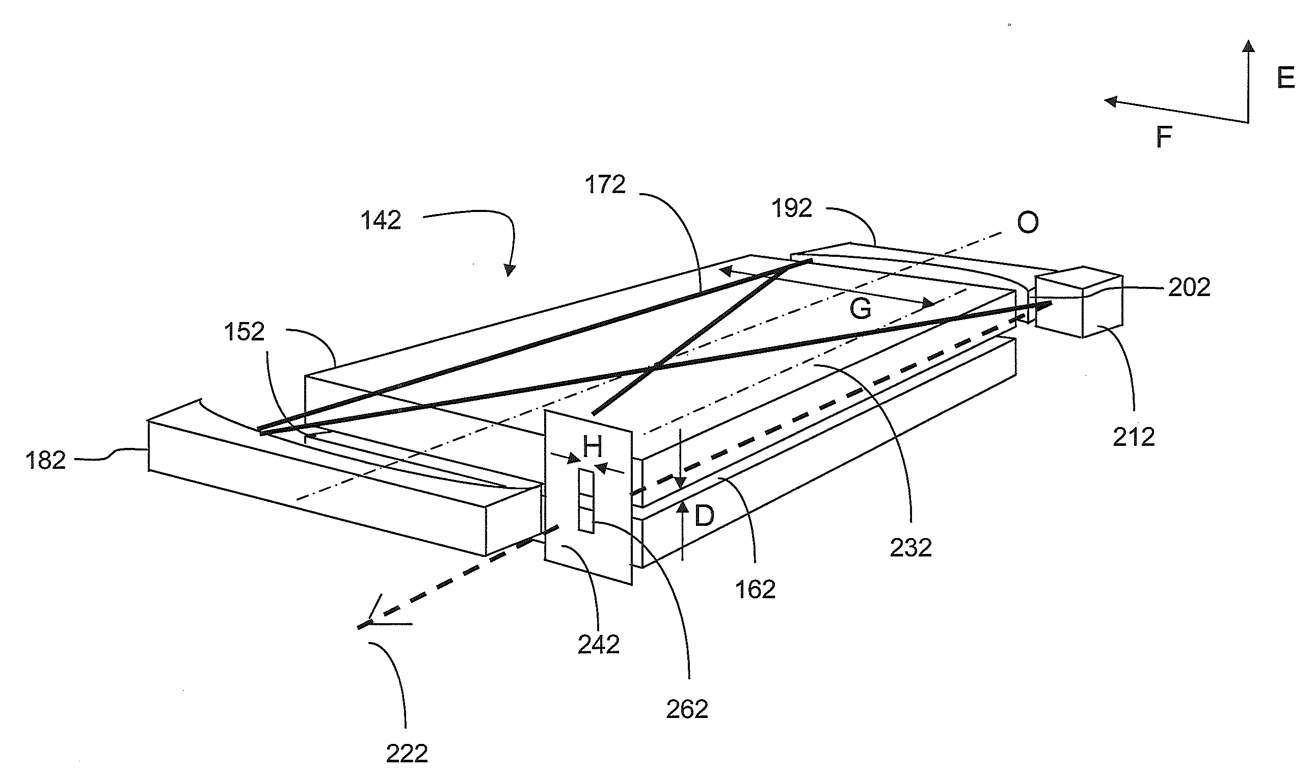
[0055]One embodiment of this invention will be described with reference to the accompanying drawings, namely FIG. 2(a), FIG. 2(b) and FIG. 2(c). FIG. 2(a) shows a perspective drawing of the optical and discharge structure of one embodiment; the gas discharge structure 142 comprises two metallic planar, rectangular electrodes 152, with the Radio Frequency excited gas discharge running in the narrow gap 162 between the electrodes. The width D of the gap 162 is usually from 1-2 mm, with the gap width D maintained to within 100 microns over the entirety of the discharge structure. This uniform gap in conjunction with the flat metallic surface of the electrodes also acts to form a waveguide for the laser resonator in the narrow transverse dimension E of the resonator. In the wider lateral free-space dimension F of the resonator defined by the width of the slab G, or alternatively the width of the resonator mirrors placed at the ends of the discharge, the laser resonator operates in this ...


PUM


Abstract

A gas laser device is presented that produces a near diffraction limited round beam exiting the discharge vessel. Through the use of a simple focusing system, additional waveguide strip and a spatial filter in conjunction with the new asymmetric hybrid planar waveguide resonator, a round diffraction limited beam can be produced exiting the discharge vessel. Furthermore, a second and very similar design is presented that allows for spatial filtering to take place directly outside of the discharge vessel, thereby enabling filtering of the beam to be an added option.

Description

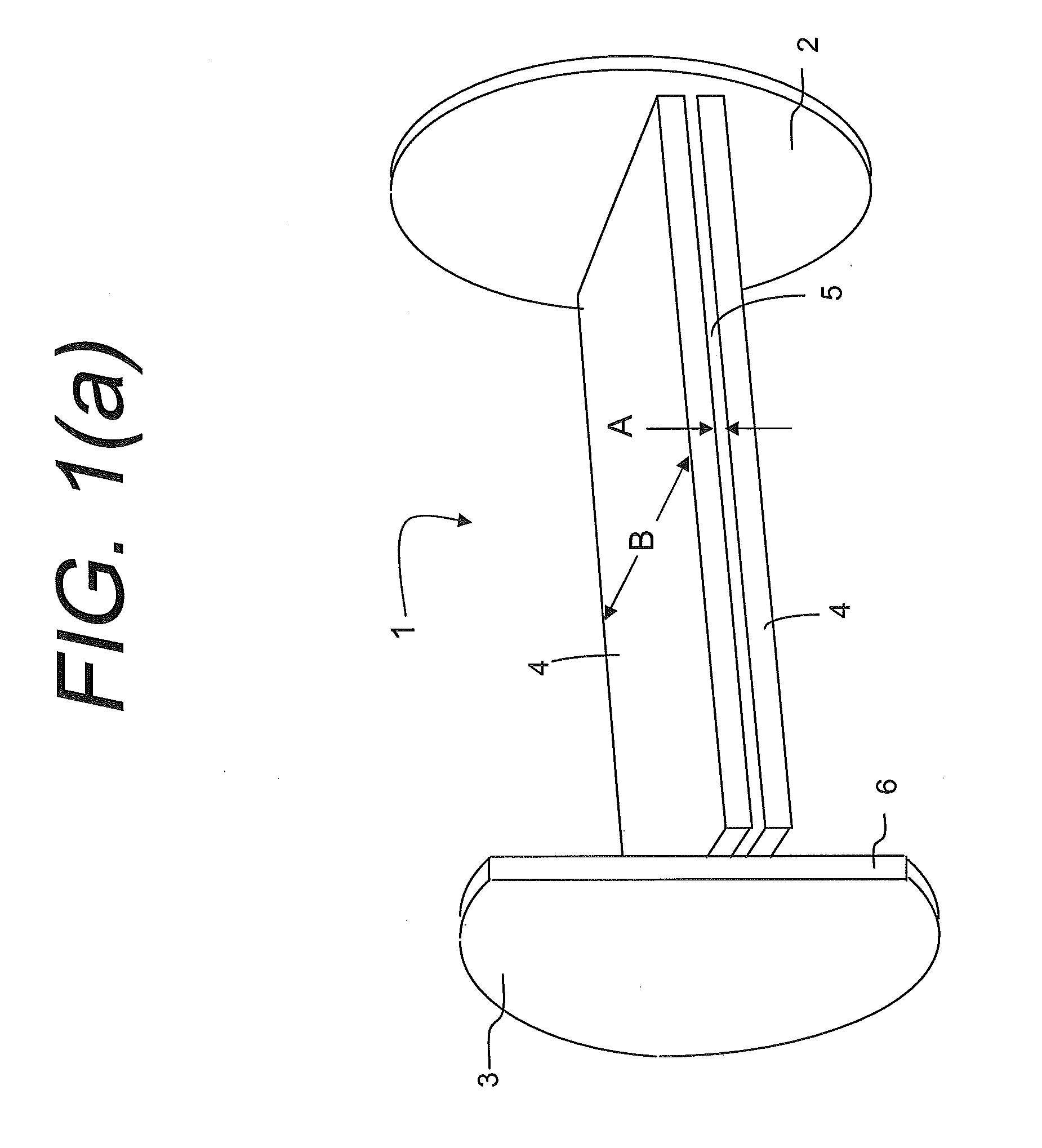
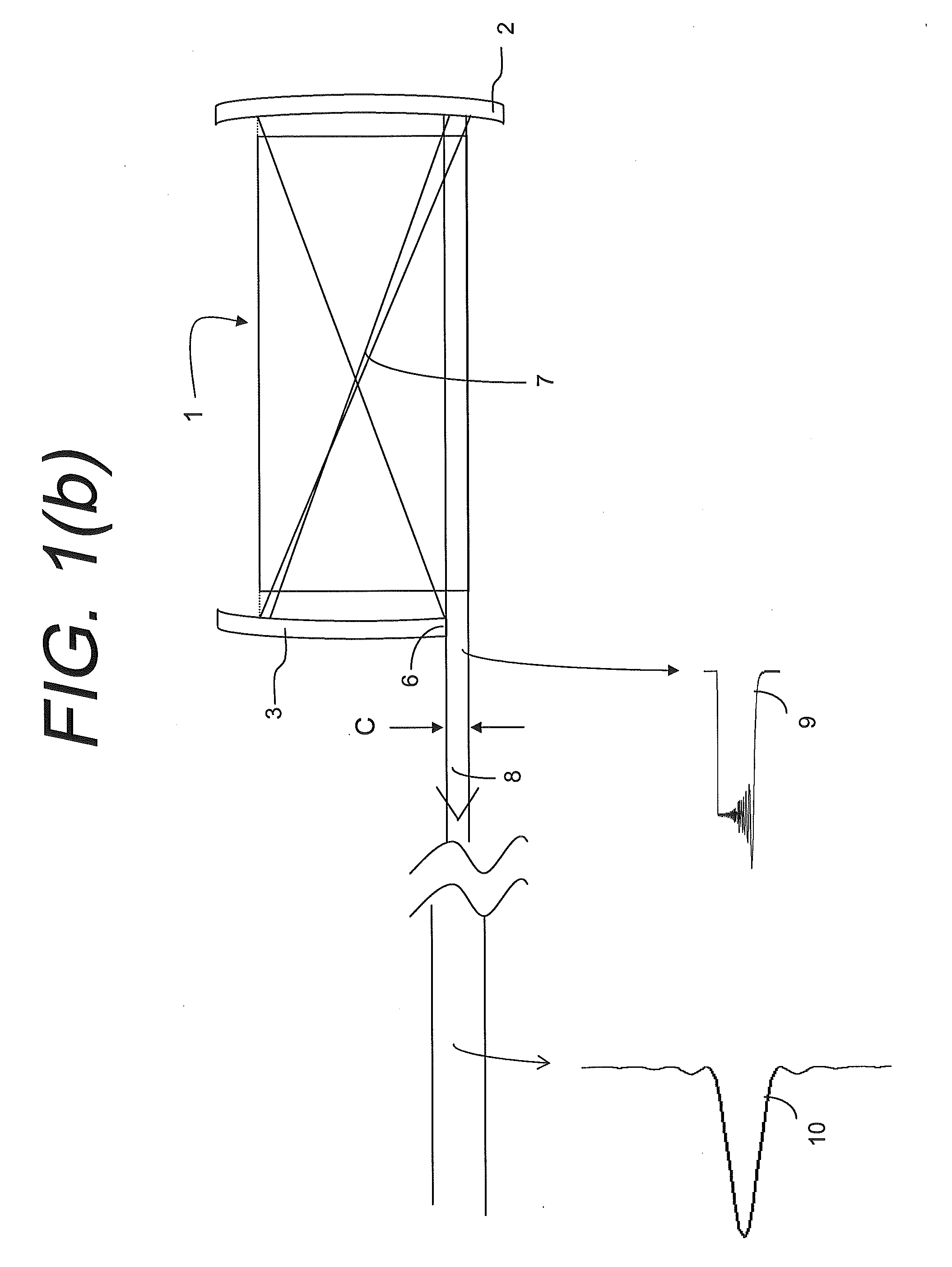
RELATED APPLICATION DATA[0001]This application claims the benefit of foreign priority under 35 U.S.C. § 119(a)-(d) from European Patent Application No. 07119271.0, filed Oct. 25, 2007, and titled “Gas Laser Device,” which is incorporated by reference herein in its entirety.FIELD OF THE INVENTION[0002]The present invention generally relates to the field of gas discharge lasers, particularly, but not limited to, an RF excited slab discharge laser vessel, operating in a wavelength region from 3 to 12 microns. In particular, the present invention is directed to a gas laser device.BACKGROUND[0003]FIG. 1(a) is a perspective view of a conventional rectangular asymmetric hybrid planar waveguide gas laser device 1 consistent with the prior art presented in U.S. Pat. No. 5,335,242 used to generate laser output wavelengths from 3 to 12 microns in length. To generate gain within the laser cavity formed between the resonator mirrors 2, 3, a Radio Frequency gas discharge is created between two me...

Claims


Application Information

Patent Timeline
Patent Type & Authority Applications(United States)
IPC IPC(8): H01S3/03
CPCG02B27/0927G02B27/0988H01S3/005H01S2301/20H01S3/0818H01S3/2232H01S3/2308H01S3/0315
Inventor MARKILLIE, GAVIN
Owner LUXINAR LTD
Learn More