Flow cell and process for producing the same

a flow cell and flow cell technology, applied in the field of flow cells, can solve the problems of high production cost, limited use of conventional flow cells, poor resistance of resins to organic solvents, etc., and achieve the effects of reducing the size of the flow cell, preventing the formation of a gap and leakage of solvents, and increasing the bonding strength between these members

Inactive Publication Date: 2009-05-07
SHIMADZU CORP
View PDF12 Cites 54 Cited by
  • Summary
  • Abstract
  • Description
  • Claims
  • Application Information

AI Technical Summary

Benefits of technology

[0028]As described above, in the case of the conventional flow cell disclosed in Patent Document 1, there is a case where a gap is formed between members constituting the flow cell only by holding both ends of the flow cell and applying pressure to both ends of the flow cell, and therefore a solvent or the like leaks from the gap. On the other hand, in the case of the flow cell according to the present invention, the flow cell is heated and pressed to allow a fluorocarbon resin interposed between members constituting the flow cell to bond these members together, thereby increasing the bonding strength between these members and therefore preventing formation of a gap and leakage of a solvent.
[0029]As described above, since the fluorocarbon resin itself bonds members constituting the flow cell together, liquid leakage is less likely to occur in the flow cell according to the present invention than in a flow cell obtained by pressing a laminate of two substrates, between which a spacer is interposed, to bring these substrates into close contact with each other. Therefore, it is not necessary for the flow cell according to the present invention to use a jig for applying pressure to substrates to keep close contact between these substrates, thereby reducing the size of the flow cell. Further, in the case of the conventional flow cell disclosed in Patent Document 1, both ends of the flow cell are pressed using screws, which makes it difficult to stack the flow cells to produce a multiple flow cell having multiple flow paths. In addition, in order to change some of the flow cells of such a multiple flow cell, it is necessary to completely disassemble the multiple flow cell. On the other hand, in the case of a multiple flow cell using the flow cells according to the present invention, the flow cells are independent of one another, and therefore some of the flow cells can be easily changed.
[0030]Further, since the flow path of the flow cell according to the present invention is formed in the fluorocarbon resin, the flow cell according to the present invention can handle organic solvents and the like which cannot be handled by conventional flow cells made of acrylic resin or polycarbonate resin.
[0031]By using an adhesive fluorocarbon resin as the fluorocarbon resin, a groove can be more easily formed in the adhesive fluorocarbon resin by molding or cutting. Therefore, it is possible to form a groove as a flow path at lower cost as compared to a case where a groove is formed in a glass substrate or a silicon substrate.
[0032]Further, by forming a metal thin film on the surface of a member to be bonded to the fluorocarbon resin, it is possible to enhance bonding strength between members constituting the flow cell according to the present invention, thereby improving the reliability of the flow cell according to the present invention. Further, by using the metal thin film as electrodes, it is also possible to allow the flow cell according to the present invention to have higher performance.BEST MODES FOR CARRYING OUT THE INVENTION
[0033]Hereinbelow, preferred embodiments of the present invention will be described with reference to the accompanying drawings. It is to be noted that these preferred embodiments use an adhesive fluorocarbon resin as a fluorocarbon resin, but a fluorocarbon resin other than the adhesive fluorocarbon resin can also be used in the present invention.

Problems solved by technology

This requires an exposure device for transferring the shape of a groove onto the plate-shaped member, facilities for a chemical solution or a reactive gas to be used, and the like, thereby resulting in high production costs.
However, resin is poor in resistance to organic solvents, and therefore, such a conventional flow cell has limited uses.

Method used


Image

  • Flow cell and process for producing the same
  • Flow cell and process for producing the same
  • Flow cell and process for producing the same

Examples


first embodiment

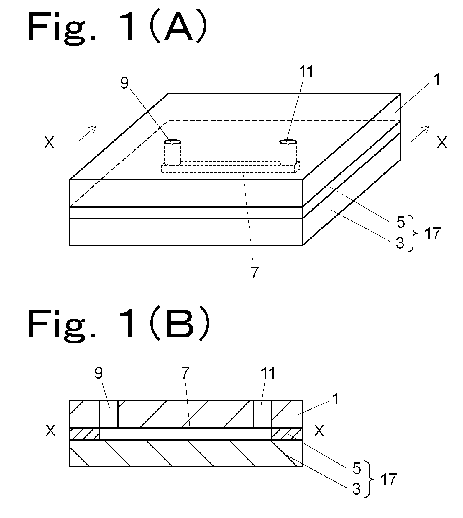
[0035]The flow cell includes a plate-shaped glass substrate 3, an adhesive fluorocarbon resin sheet 5 having a groove as a flow path 7 formed by cutting, and a glass substrate 1 as a cover member having through holes 9 and 11 as a fluid inlet and a fluid outlet formed at positions corresponding to both ends of the groove. The fluorocarbon resin sheet 5 is interposed between the glass substrates 1 and 3, and the fluorocarbon resin sheet 5 itself bonds the glass substrate 1 and the glass substrate 3 together. The glass substrate 3 and the fluorocarbon resin sheet 5 bonded to the glass substrate 3 constitute a flow path member 17.

[0036]The fluorocarbon resin sheet 5 is formed using Neoflon™ EFEP RP-4020, and therefore has a melting point of 155 to 170° C. and a decomposition temperature of 355° C.

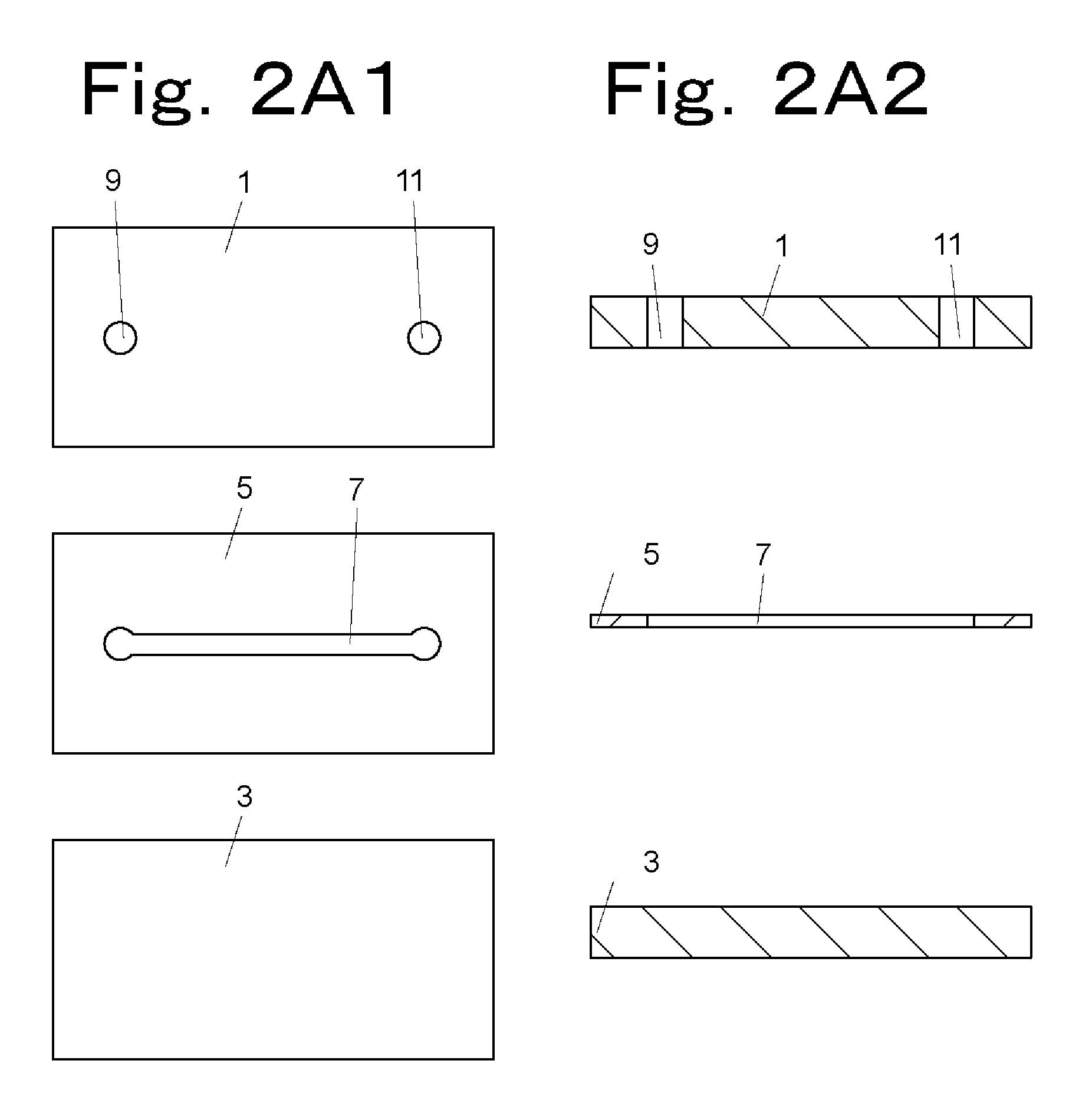
[0037]FIG. 2 is a diagram showing the process of producing a flow cell according to the first embodiment, wherein FIG. 2(A1) shows exploded plan views of members constituting the flow cell ac...

second embodiment

[0042]Hereinbelow, a flow cell according to another embodiment (a second embodiment) of the present invention will be described with reference to FIG. 3. FIG. 3(A) is a perspective view of a flow cell according to another embodiment (a second embodiment) of the present invention, and FIG. 3(B) is a sectional view taken along the X-X line in FIG. 3(A).

[0043]The flow cell according to the second embodiment includes: a fluorocarbon resin body 27 entirely made of an adhesive fluorocarbon resin and having a groove as a flow path 7 formed in the surface thereof; and a glass substrate 1 as a cover member provided to cover the groove of the fluorocarbon resin body 27. The flow cell according to the second embodiment is obtained by bonding the fluorocarbon resin body 27 and the glass substrate 1 together by means of adhesiveness of the adhesive fluorocarbon resin. The glass substrate 1 has through holes 9 and 11 formed at positions corresponding to both ends of the groove as a flow path 7, a...

third embodiment

[0052]Hereinbelow, a flow cell according to yet another embodiment (a third embodiment) of the present invention will be described.

[0053]As described above, the flow cell according to the first embodiment or the second embodiment is obtained by laminating the adhesive fluorocarbon resin sheet 5 on the glass substrate 3, or by laminating the glass substrate 1 on the fluorocarbon resin body 27 so that one end of the flow path 7 is aligned with the through hole 9 and the other end of the flow path 7 is aligned with the through hole 11. The flow cell according to the third embodiment has a metal film, such as platinum, formed by, for example, sputtering on the glass substrate 1 or the glass substrate 3 to further improve adhesion between the glass substrate and the fluorocarbon resin sheet 5 or between the glass substrate and the fluorocarbon resin body 27. By providing such a metal film on the surface of the glass substrate to be bonded to the fluorocarbon resin sheet 5 or the fluoroca...


PUM

PropertyMeasurementUnit
decomposition temperatureaaaaaaaaaa
melting pointaaaaaaaaaa

Abstract

To provide a flow cell that is free from liquid leakage and excels in chemical resistance. There is provided a preferred form of flow cell comprising flat-plate glass substrate (3); adherent fluororesin sheet (5) having a groove as flow channel (7) made by cutting machining; and glass substrate (1) as lid member furnished with through-holes (9, 11) as fluid inlet and outlet at positions corresponding to both end portions of the groove. The fluororesin sheet (5) is interposed between the glass substrates (1, 3) and, while heating at a temperature not lower than the melting point of the fluororesin sheet (5), pressurized so that the glass substrates (1, 3) are bonded together by the fluororesin sheet (5) per se. Flow channel member (17) is constructed by the glass substrate (3) and, bonded thereonto, the fluororesin sheet (5).

Description

TECHNICAL FIELD[0001]The present invention relates to a flow cell which can be used as a flowmeter or an electric conductivity meter for use in an analytical instrument, a fluorescence detector for liquid chromatography, a microchip for electrophoretic separation, or the like and a method for producing such a flow cell.BACKGROUND ART[0002]In recent years, various flow cells capable of handling a trace amount of fluid have been developed using semiconductor manufacturing techniques such as etching used to form a fine groove or the like. FIG. 7(A) is a perspective view showing one example of the structure of a conventional flow cell for handling a trace amount of fluid, and FIG. 7(B) is a sectional view taken along the X-X line in FIG. 7(A).[0003]This flow cell includes a plate-shaped member 34 having a groove as a flow path 7 formed in the surface thereof and a plate-shaped member 32 having through holes 9 and 11 formed at positions corresponding to both ends of the groove, and it is...

Claims


Application Information

Patent Timeline
Patent Type & Authority Applications(United States)
IPC IPC(8): B01L3/00B32B37/00
CPCB01L3/502707Y10T156/10B01L2200/147B01L2300/0816B01L2300/0877B01L2300/0887B01L2300/12B29C65/5057B29C66/91921B29K2027/12B29L2031/756B32B37/182B32B38/04B32B2038/047B32B2457/00G01N21/05G01N27/44721G01N27/453G01N30/74G01N2021/0346B29C66/91411B29C65/4815B29C66/53461B29C66/91221B29C66/91317B29C66/919B29C66/91931B29C66/91933B29C66/91941B29C66/91943B29C66/91214B01L2200/0689B29C66/71Y10T137/8593B29C66/1122
Inventor KANAI, MASAKIFUJIYAMA, YOICHIAKECHI, MASAKAZU
Owner SHIMADZU CORP
Why Eureka
Try Eureka