Field emission electron source having carbon nanotubes and method for manufacturing the same

a carbon nanotube and electron source technology, applied in the manufacture of discharge tube main electrodes, electric discharge tube/lamps, electric discharge tube systems, etc., can solve the problems of reducing affecting the controllability of the mechanical method, and affecting the performance of the field emission electron source. , to achieve the effect of improving the mechanical strength of the cnt string, easy control, and stable connection

Active Publication Date: 2009-05-07
TSINGHUA UNIV +1
View PDF8 Cites 25 Cited by
  • Summary
  • Abstract
  • Description
  • Claims
  • Application Information

AI Technical Summary

Benefits of technology

[0010]A method for manufacturing a field emission electron source includes: providing a CNT array; drawing a number of CNT bundles from the CNT array to form a CNT yarn; soaking the CNT yarn into an organic solvent, and shrinking the CNT yarn into a CNT string after the organic solvent volatilizing; irradiating a predetermined point of the CNT string with a laser beam; applying a voltage between two opposite ends of the CNT string, until the CNT string snapping; and attaching the snapped CNT string to a conductive base, and achieving a field emission electron source.
[0011]Compared with the conventional field emission electron source, the present field emission electron source has the following advantages: firstly, a CNT string, which is in a larger scale than the CNT, is used as the electron emitter, and thus the CNT string is more easily controlled. Secondly, the CNT string is attached to the conductive base by a conductive paste, and thus the connection is stable. Thirdly, the broken end portion of the CNT string is in a tooth-shape structure, which can prevent from the shield effect caused by the adjacent CNTs. Further, the CNT string is snapped by applying a voltage thereon, the electric and thermal conductivity, and mechanical strength of the CNT string can be improved. Therefore, the field emission efficiency of the field emission electron source is improved. Fourthly, by a laser beam irradiation, the location of the CNT string snapping can be precisely controlled, and thus the field emission electron source can be easily manufactured.

Problems solved by technology

However, the controllability of the mechanical method is less than desired, because single CNT is so tiny in size.
However, the mechanical connection between the CNTs and the conductive base often is relatively weak and thus unreliable.
In factual use, such CNTs are easy to be drawn away from the conductive base due to the electric field force, which would damage the field emission electron source and / or decrease its performance.
Furthermore, the shield effect between the adjacent CNTs may reduce the field emission efficiency thereof.

Method used


Image

  • Field emission electron source having carbon nanotubes and method for manufacturing the same
  • Field emission electron source having carbon nanotubes and method for manufacturing the same
  • Field emission electron source having carbon nanotubes and method for manufacturing the same

Examples


Embodiment Construction

[0023]Reference will now be made to the drawings to describe the preferred embodiments of the present field emission electron source and the present method, in detail.

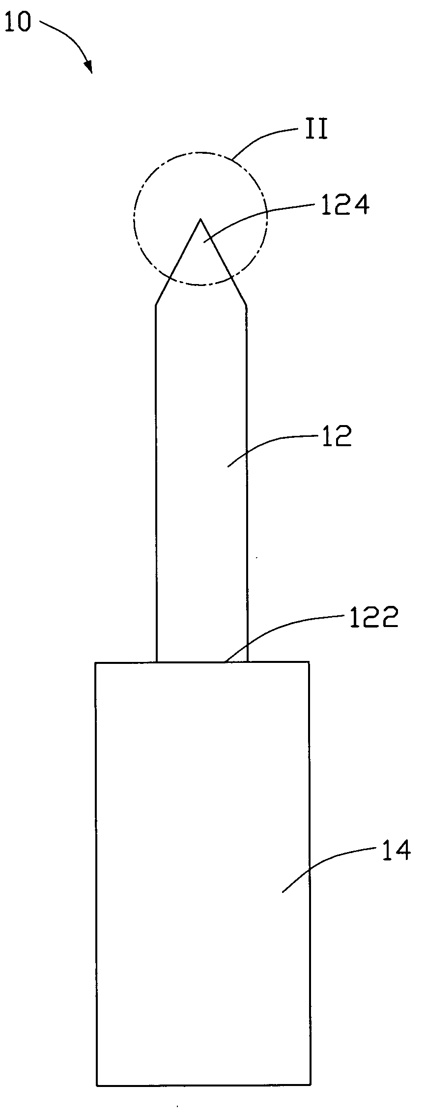
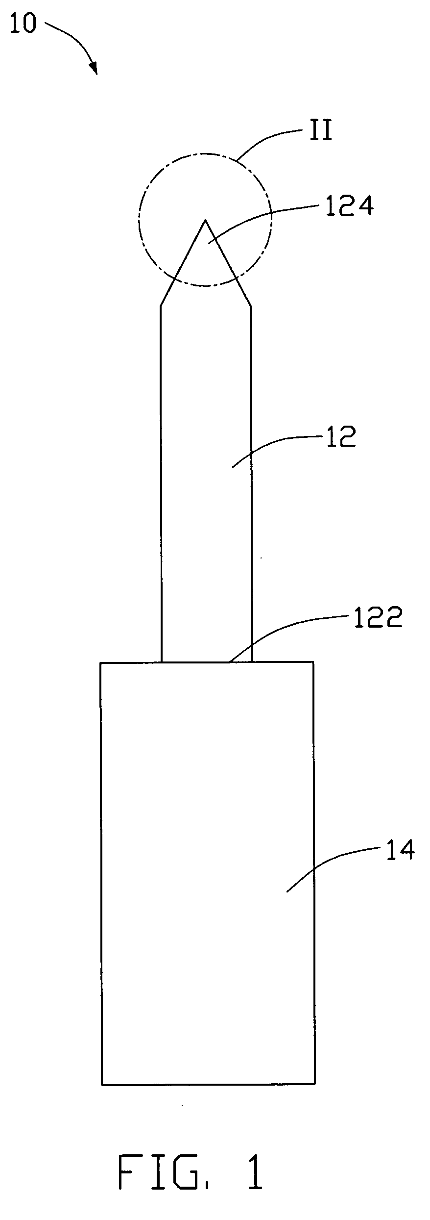
[0024]Referring to FIG. 1, a field emission electron source 10 includes a CNT string 12 and a conductive base 14. The CNT string 12 includes an end portion 122 and a broken end portion 124. The CNT string 12 is attached to the conductive base 14 with the end portion 122 being in contact with and electrically connected to the surface of the conductive base 14. The included angle between the longitudinal axis of the CNT string 12 with the surface of the conductive base 14 can be equal to or greater than 0 degree and equal to or less than 90 degrees.

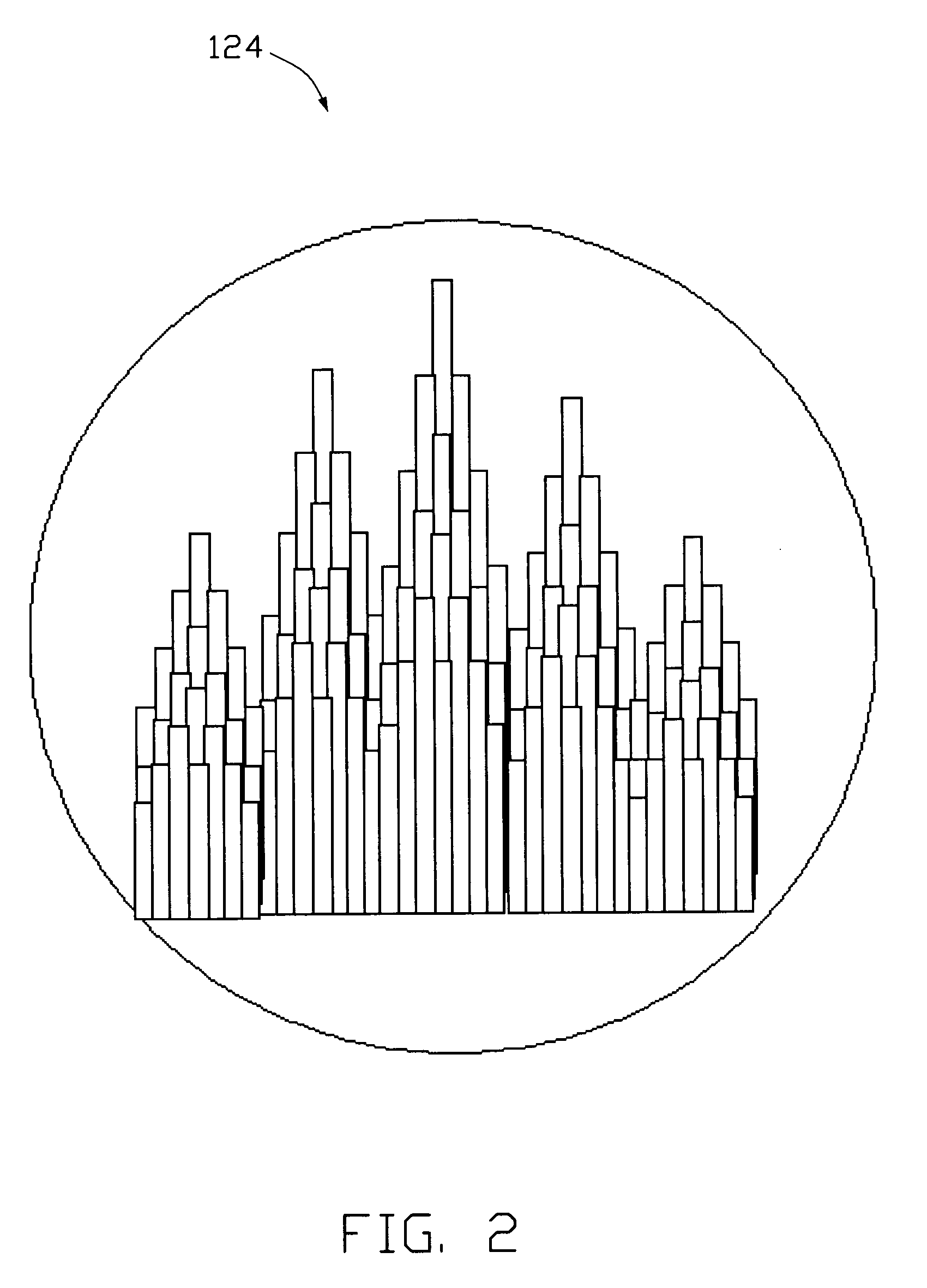
[0025]The CNT string 12 is composed of a number of closely packed CNT bundles, and each of the CNT bundles includes a number of CNTs, which are substantially parallel to each other and are joined by van der Waals attractive force. A diameter of the CNT string 12 is in an appro...


PUM


Abstract

A field emission electron source having carbon nanotubes includes a CNT string and a conductive base. The CNT string has an end portion and a broken end portion, the end portion is contacted with and electrically connected to the surface of the conductive base. The CNTs at the broken end portion form a tooth-shape structure, wherein some CNTs protruding and higher than the adjacent CNTs. Each protruding CNT functions as an electron emitter. Further, a method for manufacturing a field emission electron source is provided. The field emission efficiency of the field emission electron source is high.

Description

RELATED APPLICATIONS[0001]This application is related to commonly-assigned, co-pending application: U.S. patent application Ser. No. ______, entitled “METHOD FOR MANUFACTURING FIELD EMISSION ELECTRON SOURCE HAVING CARBON NANOTUBE”, filed **** (Atty. Docket No. US16663) and U.S. patent application Ser. No. ______, entitled “METHOD FOR MANUFACTURING FIELD EMISSION ELECTRON SOURCE HAVING CARBON NANOTUBE”, filed **** (Atty. Docket No. US16784). The disclosure of the respective above-identified application is incorporated herein by reference.BACKGROUND[0002]1. Field of the Invention[0003]The invention relates to field emission electron sources and methods for manufacturing the same and, particularly, to a field emission electron source having carbon nanotubes and a method for manufacturing the same.[0004]2. Discussion of Related Art[0005]Carbon nanotubes (CNTs) produced by means of arc discharge between graphite rods were first discovered and reported in an article by Sumio Iijima, entit...

Claims


Application Information

Patent Timeline
Patent Type & Authority Applications(United States)
IPC IPC(8): H01J1/02H01J9/02
CPCH01J1/304H01J2201/30469H01J9/025
Inventor WEI, YANGCHEN, ZHUOLIU, LIANGFAN, SHOU-SHAN
Owner TSINGHUA UNIV
Why Eureka
Try Eureka