
Design Structure for an Automatic Driver/Transmission Line/Receiver Impedance Matching Circuitry

a technology of impedance matching and design structure, which is applied in the direction of resonance circuit tuning, reliability increasing modifications, pulse techniques, etc., can solve the problems of significant voltage overshoots and undershoots, functional and performance problems, and degradation of device reliability

Inactive Publication Date: 2009-05-07
IBM CORP
View PDF24 Cites 10 Cited by
  • Summary
  • Abstract
  • Description
  • Claims
  • Application Information

AI Technical Summary

Benefits of technology

The patent text describes a design structure for a circuit that automatically matches the impedance between a driver and a receiver. The circuit includes a phase-locked loop (PLL) and impedance matching circuitry. The PLL receives a data signal from the driver and generates a frequency output based on the data signal. The impedance matching circuitry receives the data signal from the driver and provides an impedance-matched signal to the receiver. The circuit also includes a variable-capacitance capacitor that controls the impedance between the driver and the receiver. The design structure allows for efficient and accurate impedance matching between the driver and receiver, improving the overall performance of the circuit.

Problems solved by technology

For scaled CMOS technologies operating at a very high frequency, especially in the gigahertz (GHz) frequency range, the reactive component of the impedance mismatch between a receiver and a driver may cause significant voltage overshoots and undershoots.
These voltage transients are a concern because they can cause leakage currents due to forward biasing of diffusions, which may result in functionality and performance problems.
Additionally, these voltage transients may lead to degradation of device reliability and reduction of device reliability margins.
Accelerated reliability degradation occurs as a result of hot carriers as well as negative bias temperature instability.
This increase in electric field can significantly impact gate-oxide reliability and product reliability margins.

Method used


Image

  • Design Structure for an Automatic Driver/Transmission Line/Receiver Impedance Matching Circuitry
  • Design Structure for an Automatic Driver/Transmission Line/Receiver Impedance Matching Circuitry
  • Design Structure for an Automatic Driver/Transmission Line/Receiver Impedance Matching Circuitry

Examples


Embodiment Construction

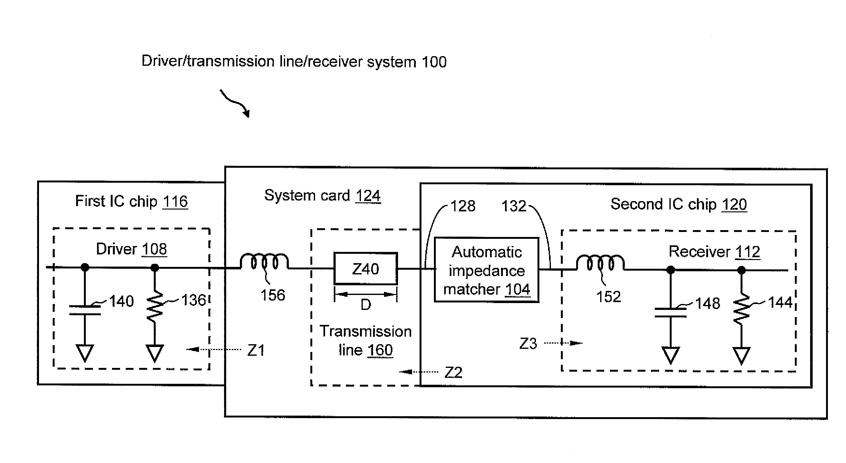
[0014]The present invention is directed to a design structure for an automatic driver / transmission line / receiver impedance matching circuitry. Referring now to the drawings, FIG. 1 illustrates an example 100 of a driver / transmission line / receiver system made in accordance with the present invention. Driver / transmission line / receiver system 100 includes an automatic impedance matcher 104 for automatically matching the impedance as between a driver and a receiver, in this example, driver 108 and receiver 112 aboard, respectively, a first integrated circuit (IC) chip 116 and a second IC chip 120. In this example, second IC chip 120 is installed on a system card 124, whereas first IC chip 116 is external to the system card. In other embodiments, driver 108 and receiver 112 may be located differently, as may be first and second IC chips 116, 120, if either or both are provided at all. Also in this example, automatic impedance matcher 104 is shown as being incorporated into second IC chi...


PUM


Abstract

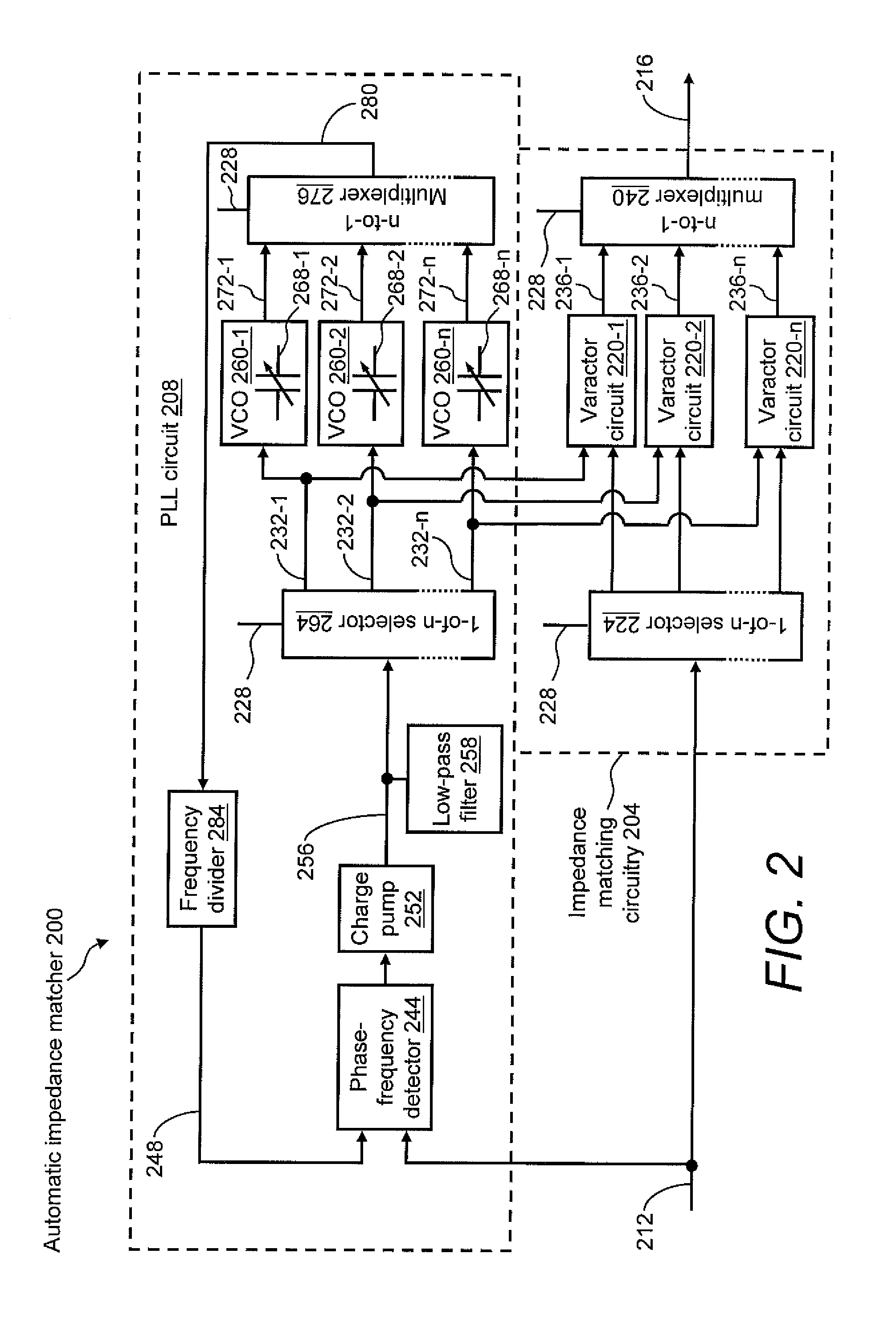
A design structure for an impedance matcher that automatically matches impedance between a driver and a receiver. The design structure for an impedance matcher includes a phase-locked loop (PLL) circuit that locks onto a data signal provided by the driver. The impedance matcher also includes tunable impedance matching circuitry responsive to one or more voltage-controlled oscillator control signals within the PLL circuit so as to generate an output signal that is impedance matched with the receiver.

Description

FIELD OF THE DISCLOSURE[0001]The present disclosure generally relates to the field of driver / transmission line / receiver impedance matching between electronic components. In particular, the present disclosure is directed to a design structure for an automatic driver / transmission line / receiver impedance matching circuitry.BACKGROUND[0002]For scaled CMOS technologies operating at a very high frequency, especially in the gigahertz (GHz) frequency range, the reactive component of the impedance mismatch between a receiver and a driver may cause significant voltage overshoots and undershoots. These voltage transients are a concern because they can cause leakage currents due to forward biasing of diffusions, which may result in functionality and performance problems. Additionally, these voltage transients may lead to degradation of device reliability and reduction of device reliability margins. Accelerated reliability degradation occurs as a result of hot carriers as well as negative bias t...

Claims


Application Information

Patent Timeline
Patent Type & Authority Applications(United States)
IPC IPC(8): H03K17/16
CPCH03J3/185H03K19/0005H03L7/0891H03L7/0805H03L7/08
Inventor ABADEER, WAGDI W.HSU, LOUIS LU-CHENMANDELMAN, JACK A.
Owner IBM CORP
Learn More