Liquid Crystal Display Device and Driving Method Thereof, Television Receiver, Liquid Crystal Display Program, Computer-Readable Storage Medium Storing the Liquid Crystal Display Program, and Drive Circuit

Inactive Publication Date: 2009-05-07
SHARP KK
View PDF15 Cites 69 Cited by
  • Summary
  • Abstract
  • Description
  • Claims
  • Application Information

AI Technical Summary

Benefits of technology

[0147]According to the above arrangement, a voltage polarity of the non-image signal applied to the data signal lines at a boundary point between the adjacent horizontal scanning periods is identical with a voltage polarity of the image signal applied in the latter horizontal scanning perio

Problems solved by technology

However, realization of impulse display by the method disclosed in Patent document 7 with an active matrix type liquid crystal display device as a hold-type display device give rise to the followi

Method used


Image

  • Liquid Crystal Display Device and Driving Method Thereof, Television Receiver, Liquid Crystal Display Program, Computer-Readable Storage Medium Storing the Liquid Crystal Display Program, and Drive Circuit
  • Liquid Crystal Display Device and Driving Method Thereof, Television Receiver, Liquid Crystal Display Program, Computer-Readable Storage Medium Storing the Liquid Crystal Display Program, and Drive Circuit
  • Liquid Crystal Display Device and Driving Method Thereof, Television Receiver, Liquid Crystal Display Program, Computer-Readable Storage Medium Storing the Liquid Crystal Display Program, and Drive Circuit

Examples


Example

First Embodiment

[0241]The following will describe an embodiment of the present invention with reference to drawings.

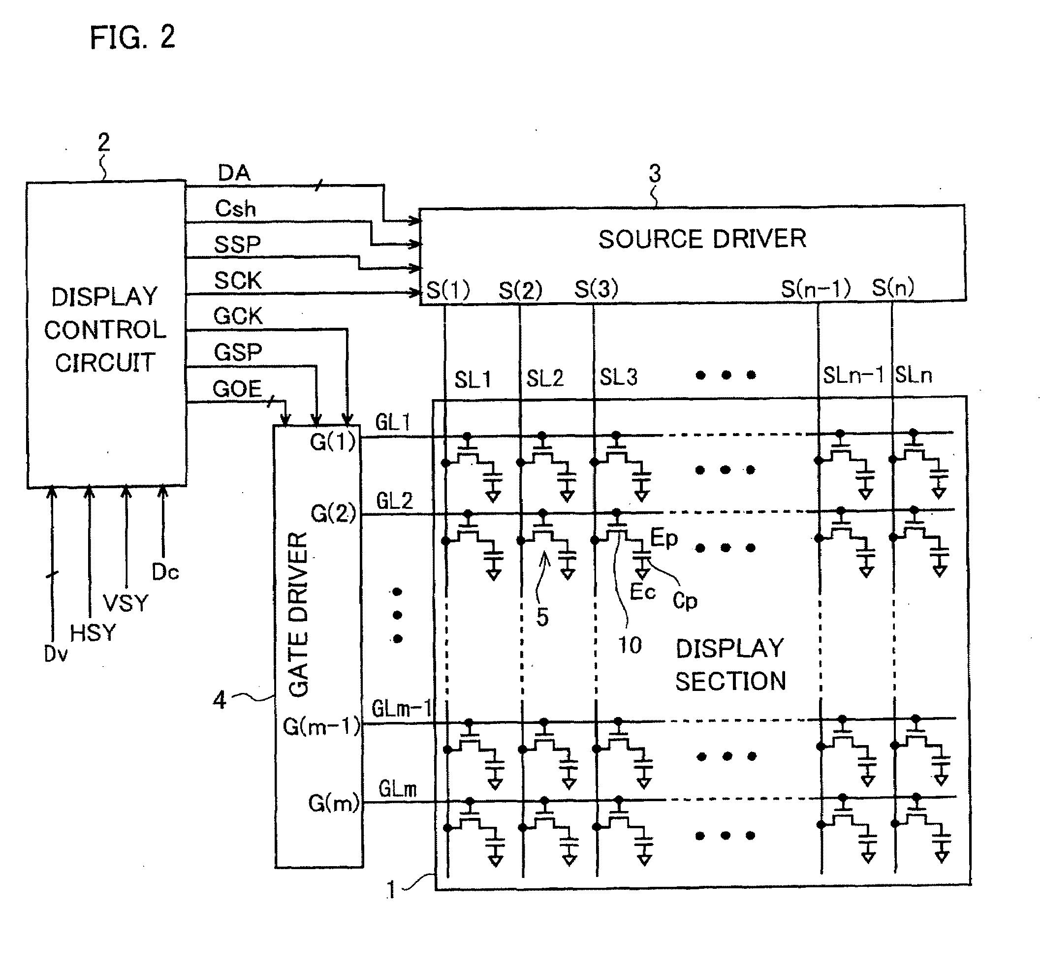
[0242]FIG. 2 is a block diagram illustrating (i) a liquid crystal display device of the present embodiment and (ii) an equivalent circuit of a display section thereof. As illustrated in FIG. 2, the liquid crystal display device includes a source driver (drive circuit) 3 as a data signal line drive circuit, a gate driver 4 as a scanning signal line drive circuit, an active matrix type display section 1, and a display control circuit 2 for controlling the source driver 3 and the gate driver 4.

[0243]The display section 1 includes a plurality of (m-number of) gate lines GL1-GLm as scanning signal lines, a plurality of (n-number of) source lines SL1-SLn as data signal lines intersecting with the gate lines GL1-GLm, a plurality of (m×n) pixel formation sections 5 which are provided at the respective intersections of the gate lines GL1-GLm and the source lines SL1-SLn.

[0244]T...

Example

Second Embodiment

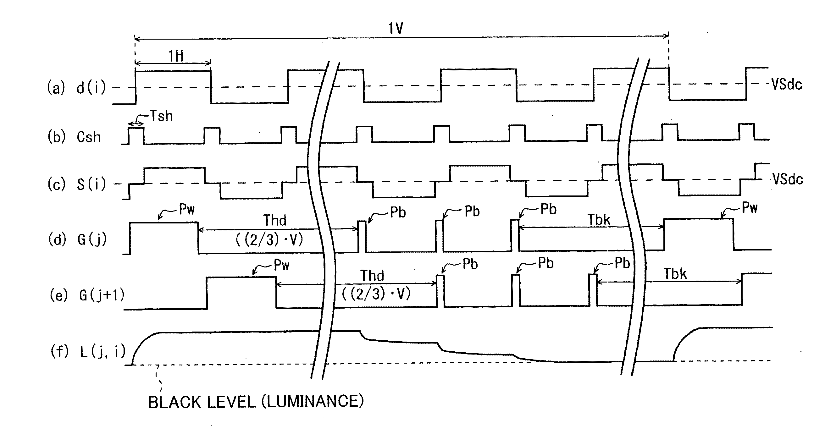
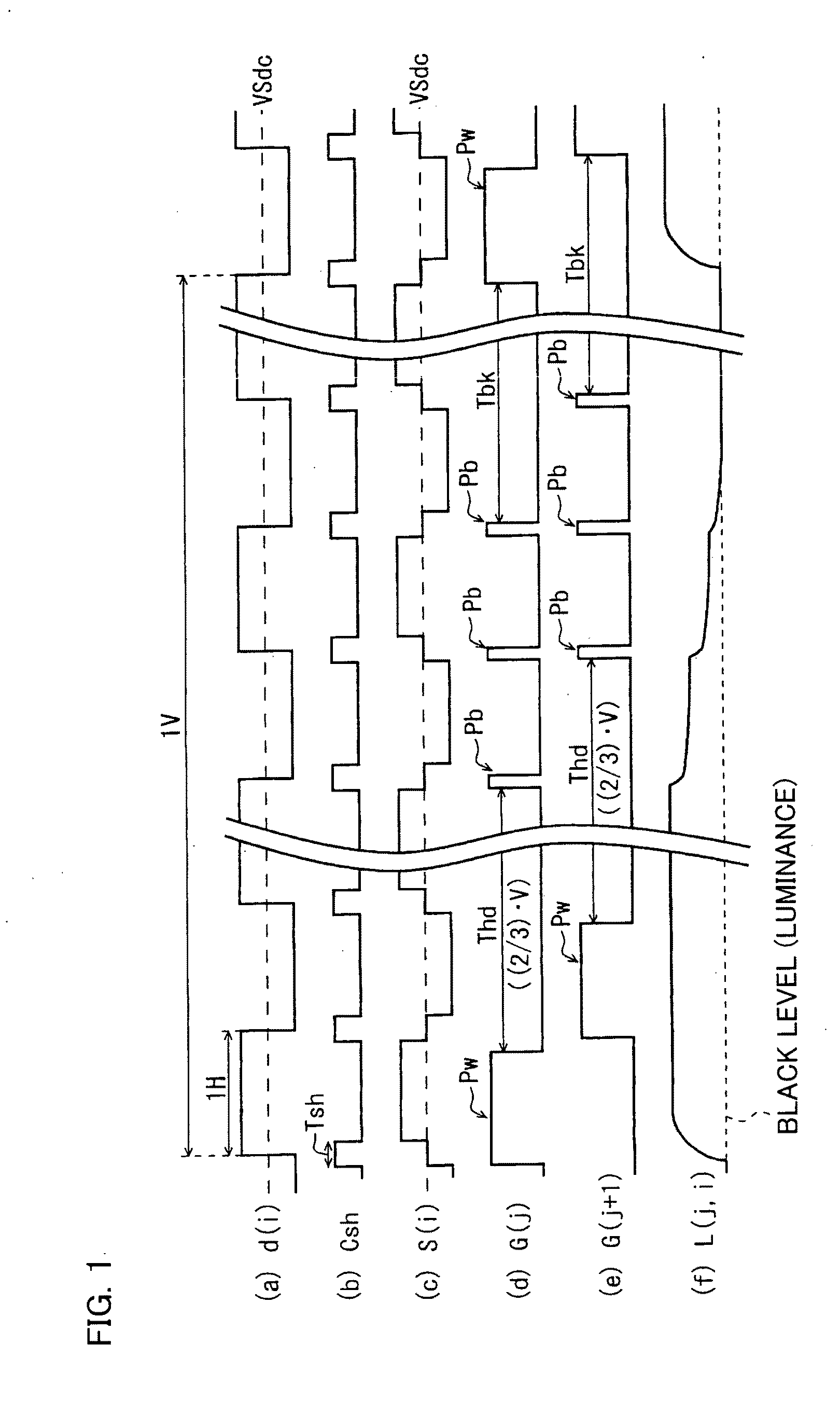
[0405]Next, the following will describe another embodiment of the present invention. A driving method of a liquid crystal display device according to the present invention may be such that polarities of pixels are reversed every plural horizontal scanning periods. The present embodiment describes a driving method of nH inversion (n is an integer not less than 2) in which the polarity of a data signal is reversed for each group of plural scanning lines.

[0406]Although First Embodiment takes as an example driving in which the polarity of a signal is reversed in each horizontal scanning period (i.e. 1H inversion driving), the present Second Embodiment is different from First Embodiment in that 2H inversion is adopted rather than 1H inversion. Explanation of the points that are in common with First Embodiment will be omitted, and only differences therebetween will be explained. Members and signals that are in common with those in First Embodiment are given the same names...


PUM


Abstract

In one embodiment of the present invention, a driving method of a liquid crystal display device is disclosed. According to one embodiment of the present invention a driving method of an active matrix display device is disclosed including: a plurality of source lines; a plurality of gate lines that intersect the source lines; and a plurality of pixel formation sections being disposed in a matrix manner at the respective intersections of the source lines and the gate lines, each of the pixel formation sections receiving as a pixel value a voltage applied to the source line that passes through the corresponding intersection when the gate line that passes through the corresponding intersection is selected, wherein non-image signals are applied to the source lines in each horizontal scanning period, and the gate lines are selected in an effective scanning period, and thereafter the gate lines are selected, in sync with a timing of application of the non-image signals to the source lines, before the subsequent effective scanning period comes after a point in time when the gate lines have been brought into non-selected state.

Description

TECHNICAL FIELD[0001]The present invention relates to an active matrix type liquid crystal display device including a switching element such as a thin-film transistor, and a driving method of the liquid crystal display device. More specifically, the present invention relates to improvement in moving image display capability of the liquid crystal display device.BACKGROUND ART[0002]As a thin, lightweight, display device capable of high-quality image display with low power consumption, a liquid crystal display device including TFTs (Thin Film Transistors) has been used in a wide range of applications, including a personal computer, a mobile telephone, and a television set. Such a liquid crystal display device is constituted by an array substrate on which TFT elements are disposed, a counter substrate on which counter electrodes are disposed, and liquid crystal which is contained in between the array substrate and the counter substrate. In recent years, various kinds of liquid crystal d...

Claims


Application Information

Patent Timeline
IPC IPC(8): G09G5/00G09G3/36
CPCG09G3/342G09G3/3614G09G3/3648G09G3/3677G09G2340/16G09G2320/0252G09G2320/043G09G2330/023G09G3/3688
Inventor SHIOMI, MAKOTOUCHIDA, TOSHIHISATSUBATA, TOSHIHIDESAWAHATA, JUNICHIYAMADA, NAOSHI
Owner SHARP KK
Why Eureka
Try Eureka