Hydrocarbon Retaining System for Flex-Fuel Combustion Engine

a technology of hydrocarbon retaining system and combustion engine, which is applied in the direction of exhaust treatment electric control, combustion-air/fuel-air treatment, electrical control, etc., can solve the problems of inefficient trapping and combustion of a second fuel composition, and achieve the effect of reducing the alcohol content of fuels, reducing the breakthrough of the hydrocarbon retaining system, and high alcohol conten

Inactive Publication Date: 2009-05-14
FORD GLOBAL TECH LLC
View PDF75 Cites 65 Cited by
  • Summary
  • Abstract
  • Description
  • Claims
  • Application Information

AI Technical Summary

Benefits of technology

[0006]Thus, the routing can be adjusted to the particular fuel properties of the fuel combusted in the engine. In the particular example where the fuel property includes a fuel alcohol content, it is possible to adjust the routing to take advantage of increased opportunity to store hydrocarbons with higher alcohol content fuels. Likewise, it is possible to reduce breakthrough of the hydrocarbon retaining system with lower alcohol content fuels.

Problems solved by technology

As such, an appropriate control to reduce or end trapping for combustion of one fuel composition may lead to breakthrough, or inefficient trapping, for combustion of a second fuel composition.

Method used


Image

  • Hydrocarbon Retaining System for Flex-Fuel Combustion Engine
  • Hydrocarbon Retaining System for Flex-Fuel Combustion Engine
  • Hydrocarbon Retaining System for Flex-Fuel Combustion Engine

Examples


third embodiment

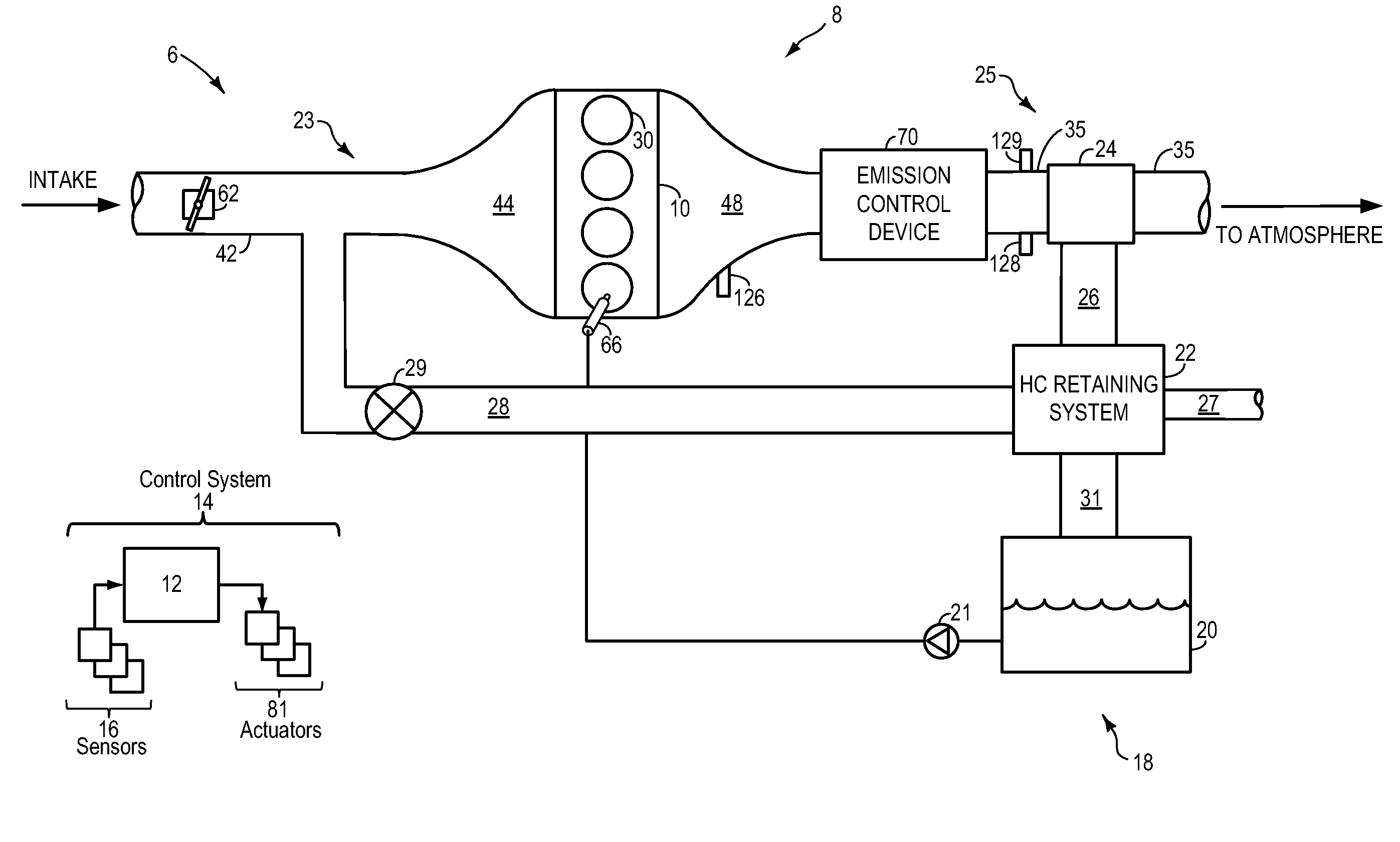
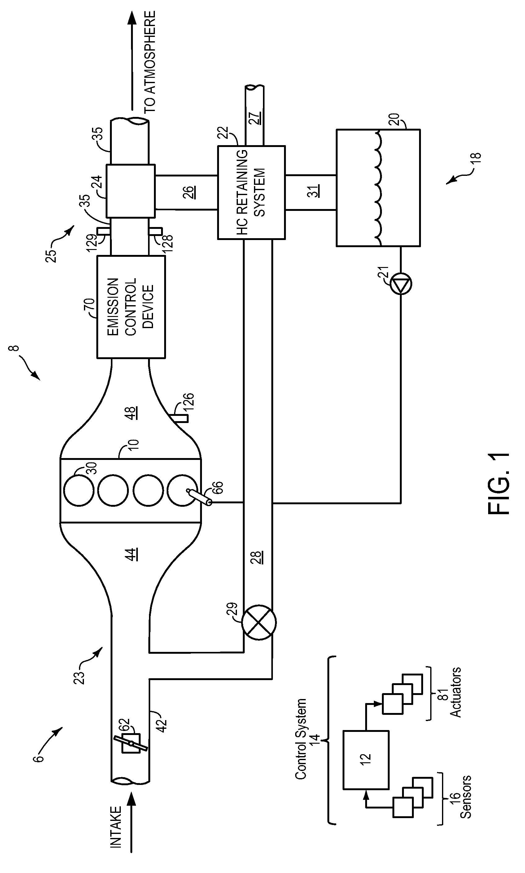
[0056]FIG. 5 shows a schematic depiction of the hydrocarbon retaining system 22. This embodiment is similar to that of FIG. 3, except that the HC trap 510 includes two bricks 520, and is configured to pass exhaust gasses serially through the bricks, but purge them in parallel. Specifically, the system of FIG. 5 includes HC trap 510 arranged in parallel with exhaust conduit 35, downstream of the emission control device 70. An exhaust conduit valve 24, which in this example may be a throttle, is located in the exhaust conduit for blocking exhaust flow during a first mode, and allowing exhaust flow to pass during a second mode. A bypass conduit 512 is coupled upstream and downstream of the exhaust conduit valve 24. Further, the bypass conduit 512 includes a first bypass valve 514, the HC trap 510, and a second bypass valve 518. The bypass conduit 512 is also coupled to vent 27 via two parallel passages 534 and valve 538.

[0057]Furthermore, the HC trap 510 is fluidly coupled to a purge c...

fourth embodiment

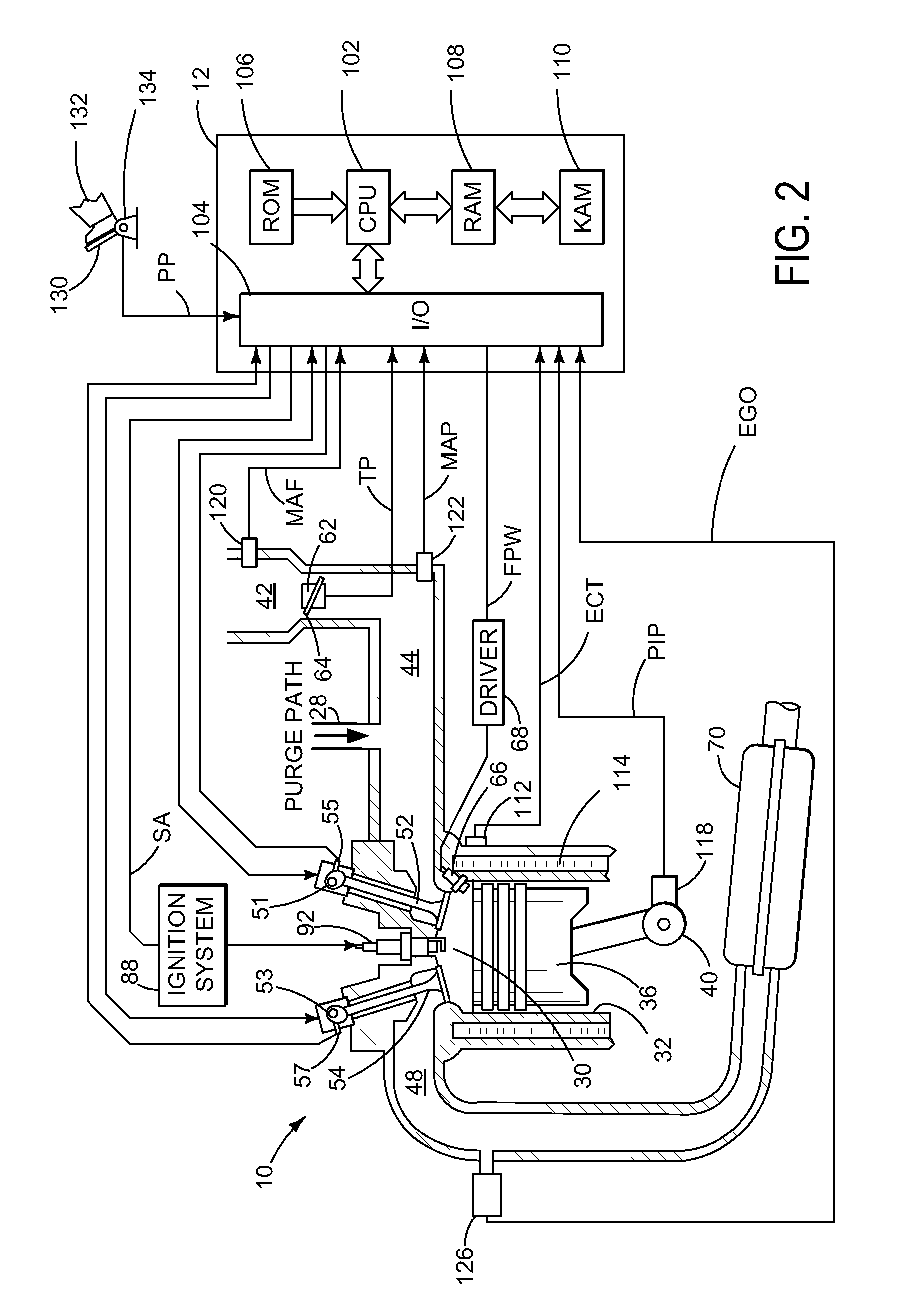
[0070]FIG. 7 shows a hydrocarbon retaining system 22. This example is similar to that of FIG. 4, although different valve and conduit configurations are used, along with two HC traps, in bypass 712. Specifically, in this example, valve 24 operates as a diverter valve to either allow exhaust gas flow through conduit 35 to atmosphere, or to direct the exhaust gas flow to conduit 714 and valve 716. In this example, valve 716 is another diverter valve which either allows communication between conduit 714 and conduit 740, or conduit 714 and conduit 742. Bypass 712 further includes a first and second HC trap, 726 and 728, respectively. Further still, a valve 726 is shown for controlling flow leading to, or coming from, the purge canister (not shown), which then leads to the fuel tank and intake manifold, similar to the other example configurations described above. As such, fuel vapors from the fuel tank may be routed to the first and second traps, 726 and 728, in that order, and purged in...


PUM


Abstract

Systems, methods, and computer readable storage media are described in which exhaust gas is routed to a hydrocarbon retaining device during starting, and purged to the engine intake manifold. Various alternative approaches are described for controlling operation and diagnosing degradation. Further, various interrelated configurations are described.

Description

[0001]The present application claims priority to provisional application 60 / 987,350, filed Nov. 12, 2007, the entire contents of which are incorporated herein by reference for all purposes.FIELD[0002]The present description relates generally to an exhaust treatment system for a combustion engine.BACKGROUND / SUMMARY[0003]Engine exhaust systems have utilized hydrocarbon retaining devices, such as hydrocarbon traps, to retain cold start emissions for later reaction, or to recirculate into the engine intake system. In one particular example, the trapping of exhaust gases may be ended when the device reaches a predetermined temperature.[0004]However, the inventors herein have recognized several issues with such examples. Specifically, the engine may operate with varying fuel compositions thereby producing exhaust emissions that may have different adsorption and / or desorption characteristics. For example, flex-fuel vehicles that operate on fuel having a varying alcohol composition (e.g., r...

Claims


Application Information

Patent Timeline
Patent Type & Authority Applications(United States)
IPC IPC(8): F01N9/00
CPCF02D41/0025F02D19/088F02M25/0809F02M25/0854F02M25/089Y02T10/36F01N5/02F02B23/104F02B2075/125F02D13/0207F02D13/0219Y02T10/123Y02T10/16F02D19/084F02D41/062Y02T10/12Y02T10/30
Inventor GANDHI, HARENDRA S.UHRICH, MICHAEL JAMESELWART, SHANEKERNS, JAMES MICHAELLUPESCU, JASON AARON
Owner FORD GLOBAL TECH LLC
Why Eureka
Try Eureka