Earth-boring tools attachable to a casing string and methods for their manufacture

a technology of earth-boring tools and casings, which is applied in the field of earth-boring tools and methods of forming earth-boring tools, can solve the problems of high cost of operations, time-consuming and labor-intensive sequence drilling and casing, and inability to recover drill strings, etc., and achieves the effect of convenient drilling

Active Publication Date: 2009-05-14
BAKER HUGHES INC
View PDF21 Cites 56 Cited by
  • Summary
  • Abstract
  • Description
  • Claims
  • Application Information

AI Technical Summary

Benefits of technology

[0008]The present invention is directed to earth-boring tools and methods for forming earth-boring tools attachable to a casing string which are more easily drilled through. Various embodiments of the present invention comprise a bit crown for use in drilling a bore hole with casing. In one or more embodiments, the bit crown may comprise a substantially hollow body comprising a generally rounded face at one longitudinal end thereof. Two or more blades may extend generally radially outward over the face from a center of the face. At least one blade of the two or more blades may comprise a recess extending from inside the substantially hollow body into a portion of the at least one blade. A plurality of cutting elements may be attached to each of the two or more blades.
[0009]Other embodiments comprise an earth-boring tool attachable to a casing string. One or more embodiments of such earth-boring tools may comprise a crown comprising a generally cylindrical hollow body. The hollow body may comprise an open end and a longitudinally opposing, closed end. The closed end of the hollow body may comprise a generally rounded face. A plurality of blades may be positioned on the face and may extend radially outward from the face. A plurality of cutting elements may be attached to the plurality of blades. At least some of the plurality of cutting elements may comprise polycrystalline diamond compact material bonded to a short substrate on which the PDC material is formed. A structural inlay comprising a composite material may be positioned at least within a portion of the hollow body.
[0010]Still other embodiments of the present invention comprise methods for forming earth-boring tools which may be attachable to a casing string. One or more embodiments of such methods may comprise forming a bit body comprising a face at one longitudinal end thereof and a substantially hollow interior. At least one blade may be formed and located to extend radially over the face. One or more cutting elements may be attached to the at least one blade. An inlay may be formed of a composite material and may be positioned at least inside a portion of the hollow interior of the bit body.

Problems solved by technology

Unfortunately, sequential drilling and casing may be time consuming because, as may be appreciated, at the considerable depths reached during oil and gas production, the time required to implement complex retrieval procedures to recover the drill string may be considerable.
Thus, such operations may be costly as well, since, for example, the beginning of profitable production can be greatly delayed.
Moreover, control of the well may be difficult during the period of time that the drill pipe is being removed and the casing is being disposed into the borehole.
While this procedure greatly increases the efficiency of the drilling procedure, a further problem is encountered when the casing is cemented upon reaching the desired depth.
Drilling through the previous drill bit in order to advance may be difficult, as drill bits are required to remove rock from formations and, accordingly, often include very drilling resistant, robust structures typically manufactured from materials such as tungsten carbide, polycrystalline diamond, or steel.
Attempting to drill through a drill bit affixed to the end of a casing may result in damage to the subsequent drill bit and bottom-hole assembly deployed or possibly the casing itself.
It may be possible to drill through a drill bit or a casing with special tools known as mills, but these tools are unable to penetrate rock formations effectively and the mill would have to be retrieved or “tripped” from the hole and replaced with a drill bit.
In this case, the time and expense saved by drilling with casing would have been lost.

Method used


Image

  • Earth-boring tools attachable to a casing string and methods for their manufacture
  • Earth-boring tools attachable to a casing string and methods for their manufacture
  • Earth-boring tools attachable to a casing string and methods for their manufacture

Examples


Embodiment Construction

[0015]The illustrations presented herein are, in some instances, not actual views of any particular drill bit or structural inlay, but are merely idealized representations which are employed to describe the present invention. Additionally, elements common between figures may retain the same numerical designation.

[0016]In the following description, certain terminology is used to describe certain features of one or more embodiments of the invention. For instance, the term “drill-out diameter” refers to the inner diameter of a casing drill bit which may be drilled through by a subsequent drill bit run within the casing string in order to continue the borehole beyond the depth where the casing bit has been positioned.

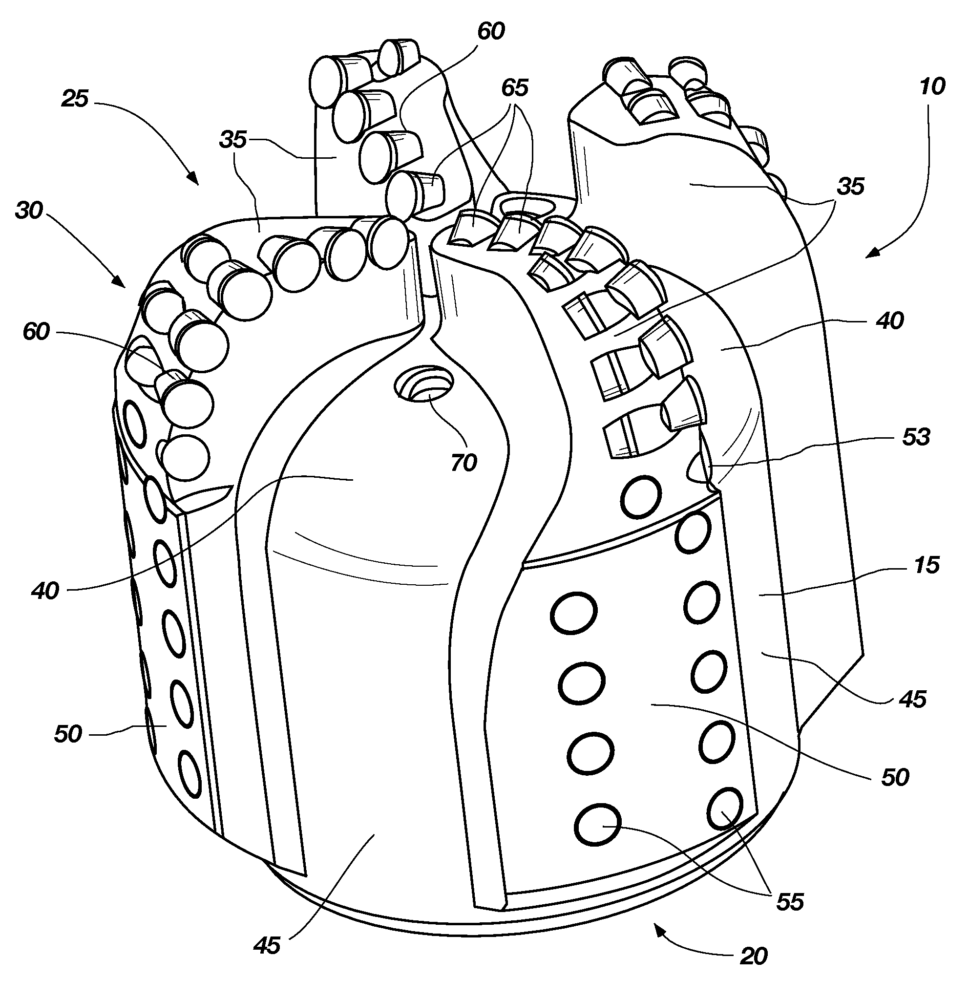
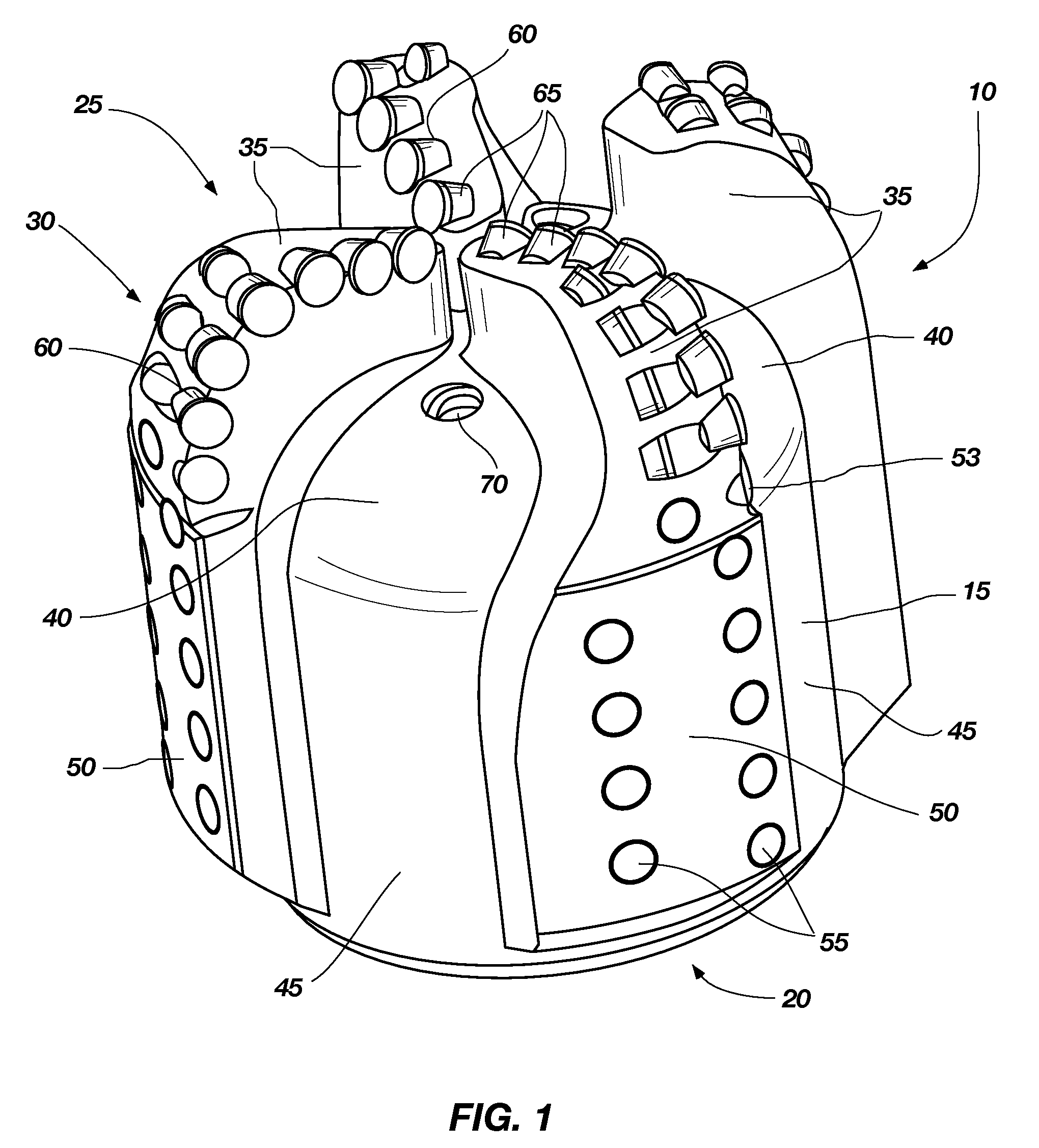
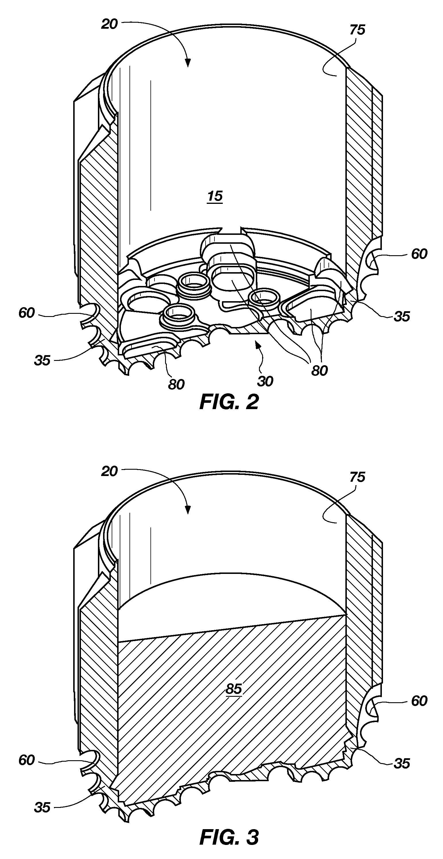
[0017]Various embodiments of the present invention are directed toward embodiments of earth-boring tools configured for drilling with casing, conventionally known as “casing bits.”FIG. 1 is an isometric views of a casing bit crown 10 according to at least some embodiments o...


PUM

PropertyMeasurementUnit
thicknessaaaaaaaaaa
thicknessaaaaaaaaaa
lengthaaaaaaaaaa

Abstract

Casing bits include a crown having a substantially hollow interior. The bit crown has blades over a face portion thereof, the blades including a plurality of cutting elements attached thereto. The bit crown further includes a composite inlay positioned at least within the substantially hollow interior. Casing bits also include case hardened outer surfaces radially outside the drill-out region. Casing bits further include short-substrate cutting elements. Methods of forming a casing bit are also disclosed.

Description

CROSS REFERENCE TO RELATED APPLICATION[0001]This application claims the benefit of U.S. Provisional Patent Application Ser. No. 60 / 987,848, filed Nov. 14, 2007, the disclosure of which is incorporated herein by reference in its entirety.TECHNICAL FIELD[0002]The present invention, in various embodiments, relates generally to earth-boring tools and methods of forming earth-boring tools. More particularly, embodiments of the present invention are directed to earth-boring tools and methods for forming earth-boring tools attachable to a casing string.BACKGROUND[0003]Drilling wells for oil and gas production conventionally employs a longitudinally extending “string” comprising sections of drill pipe with heavy walled drill “collars” at the end to which is secured a drill bit of a larger diameter than the pipe. After a selected portion of the bore hole has been drilled, a string of tubular members of lesser diameter than the bore hole, known as a casing string, is placed in the bore hole. ...

Claims


Application Information

Patent Timeline
Patent Type & Authority Applications(United States)
IPC IPC(8): E21B10/46E21B10/00B23P11/00E21B7/20E21B10/633
CPCE21B7/20Y10T29/49966E21B10/64E21B10/42
Inventor MCCLAIN, ERIC E.ISBELL, MATTHEW R.OLDHAM, JACK THOMASTHOMAS, JOHN C.BIRD, MARC W.
Owner BAKER HUGHES INC
Why Eureka
Try Eureka