LED module for illumination

a technology of led modules and led elements, which is applied in the direction of discharge tubes luminescnet screens, semiconductor devices for light sources, lighting and heating apparatus, etc., can solve the problems of limited heat radiation of led elements in large scale, led elements may be damaged, and the thermal resistance between led elements and radiators is minimized, and the life span of led elements can be extended

Inactive Publication Date: 2009-05-14
KIM WEON
View PDF9 Cites 61 Cited by
  • Summary
  • Abstract
  • Description
  • Claims
  • Application Information

AI Technical Summary

Benefits of technology

[0010]In an LED module for illumination according to the present invention, there is an advantage in that thermal resistance between an LED element and a radiator is minimized to enhance heat radiation performance of the LED module, so that the life span of the LED element can be extended and maintenance costs of a device can be reduced.
[0011]Further, there is an advantage in that there can be provided an LED lighting apparatus with superior illumination performance considering power consumption by enhancing light emitting efficiency of the LED lighting apparatus.

Problems solved by technology

For this reason, there is a problem in that an LED element may be damaged due to a large amount of heat generated from the LED element.
However, since heat transfer from the LED elements to the lower radiator is hindered by the flexible PCB with low thermal conductivity and the adhesive agent, which are positioned between the LED elements and the radiator, there is limitation to radiate a large amount of heat generated by integrating the LED elements in a large scale.
Consequently, there is a problem in that an LED element may be damaged due to heat generated in light emission.

Method used


Image

  • LED module for illumination
  • LED module for illumination
  • LED module for illumination

Examples


second embodiment

[0041]Hereinafter, an LED module for illumination according to the present invention will be described with reference to FIG. 4.

[0042]The LED module for illumination according to the second embodiment of the present invention has the same structure as the aforementioned first embodiment except the lower light emitting film 41.

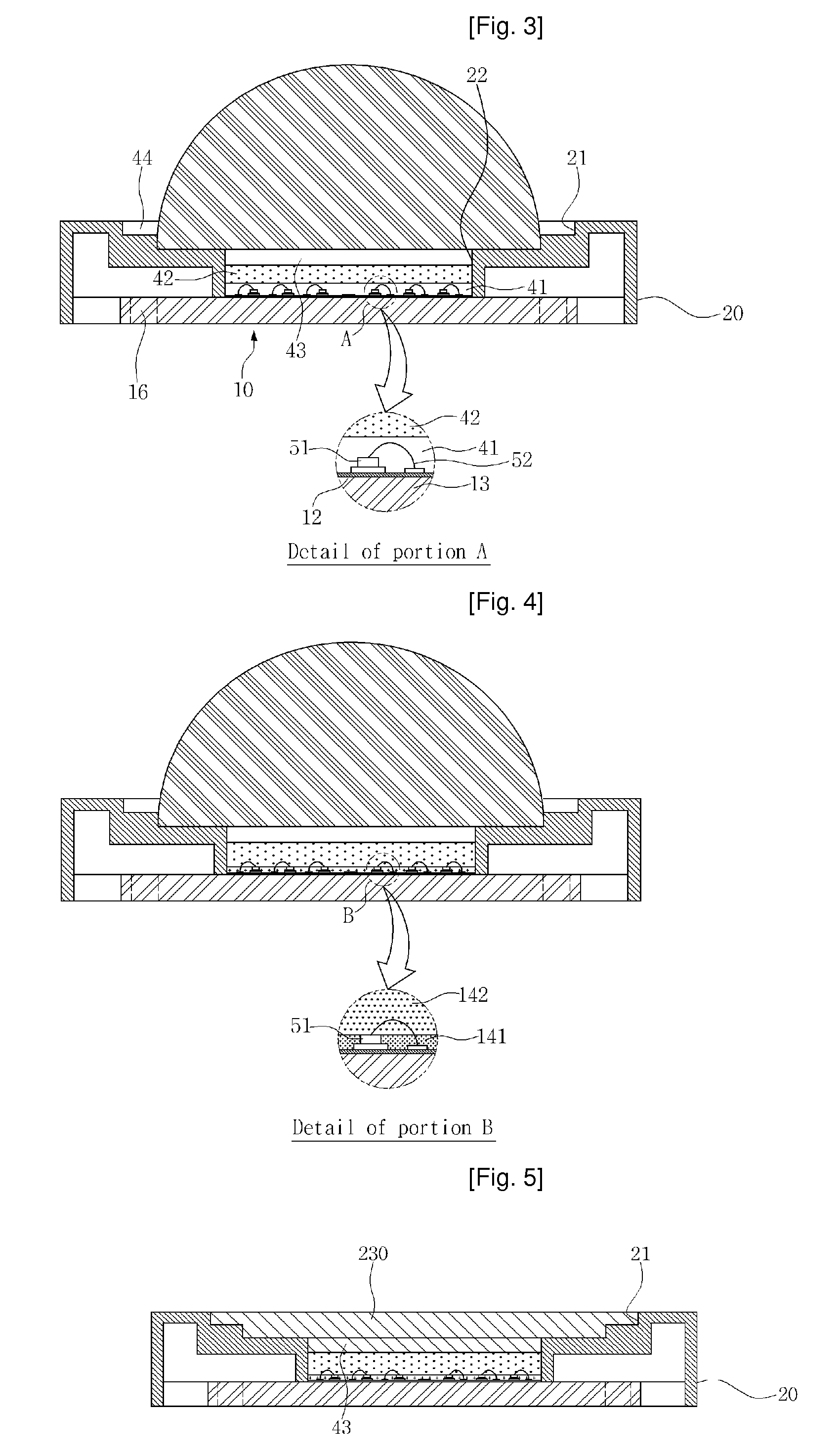
[0043]FIG. 4 is a sectional view of the LED module for illumination according to the second embodiment of the present invention.

first embodiment

[0044]As shown in FIG. 4, in the LED module for illumination according to this embodiment, a lower light emitting film 141 is formed of not clear silicon as described in the aforementioned first embodiment but a reflective material with excellent reflectivity. Here, it is preferred that epoxy resin containing Al2O3 with superior reflectivity therein be used as the reflective material. Further, the lower light emitting film 141 is formed such that only a side surface of an LED element 51 is surrounded with the reflective material by adjusting a coating amount of the lower light emitting film such that a top surface of the lower light emitting film 141 is flush with the top surface of the LED element 51. Thus, blue light emitted from the top surface of the LED element 51 is introduced into a phosphor film 142 formed on the lower light emitting film without any interference, and a component emitted downward from the phosphor film 142 among the white light emitted using blue light as ex...

third embodiment

[0046]Hereinafter, an LED module for illumination according to the present invention will be described with reference to FIG. 5.

[0047]As shown in FIG. 5, in the LED module for illumination according to this embodiment, a plane lens 230 with a flat top surface is formed by removing the semi-spherical lens 30 from the LED module for illumination according to the aforementioned second embodiment and by filling an entire space of a lens groove 21 of a case 20 from a top surface of an upper light emitting film 43 coated on a phosphor film 42 with clear silicon or epoxy resin, which is a transparent material. The LED module for illumination is used as a lighting apparatus by easily attaching a surface of the plane lens 230 to a glass window, a glass door or the like.

[0048]Further, it will be apparent that such a modification may be identically applied to the aforementioned first embodiment.

[0049]The present invention described above is not limited to the aforementioned embodiments and the...


PUM


Abstract

The present invention relates to an LED module for illumination, and more particularly, to an LED module for illumination capable of enhancing light emitting efficiency by having a light emitting structure, in which the thickness of an insulation substrate with an electrode pattern formed on a top portion thereof is minimized, a heat radiation substrate is formed by integrally attaching a radiator to a bottom surface of the insulation substrate, and LED elements are attached to the electrode pattern of the heat radiation substrate through silver epoxy with excellent heat conductivity as an adhesive agent, so that heat generated from the LED elements can effectively radiate through the radiator, white light is effectively generated from the light emitted from the LED elements, and the white light can be emitted to the outside maximally.

Description

TECHNICAL FIELD[0001]The present invention relates to an LED module for illumination, and more particularly, to an LED module for illumination capable of enhancing light emitting efficiency by having a light emitting structure, in which the thickness of an insulation substrate with an electrode pattern formed on a top portion thereof is minimized, a heat radiation substrate is formed by integrally attaching a radiator to a bottom surface of the insulation substrate, and LED elements are attached to the electrode pattern of the heat radiation substrate through silver epoxy with excellent heat conductivity as an adhesive agent, so that heat generated from the LED elements can effectively radiate through the radiator, white light is effectively generated from the light emitted from the LED elements, and the white light can be emitted to the outside maximally.BACKGROUND ART[0002]A light emitting diode (LED) has been developed using a characteristic in which a light emitting phenomenon o...

Claims


Application Information

Patent Timeline
Patent Type & Authority Applications(United States)
IPC IPC(8): F21V33/00F21K99/00
CPCF21K9/00F21Y2101/02F21V3/02F21Y2115/10E04G19/006
Inventor YOON, YOUNG ROKANG, WOO SUK
Owner KIM WEON
Why Eureka
Try Eureka