Liquid receptacle for a vehicle

Inactive Publication Date: 2009-05-21
VOLVO LASTVAGNAR AB
View PDF12 Cites 59 Cited by
  • Summary
  • Abstract
  • Description
  • Claims
  • Application Information

AI Technical Summary

Benefits of technology

[0009]current components can be decreased. Hereby, the risk for leakage can be reduced. Reduced length of conduits and hoses also implies decreased costs. Furthermore, since the first unit can be used as a bracket for the pump and/or the filter, the number of components and the requisite packaging space on the frame can be reduced. The number of attachment points on the frame can also be reduced, and the mounting of the components on the vehicle can be facilitated.
[0010]If the liquid in the receptacle and the components used for transportation of the liquid have to be heated so as to avoid freezing thereof, the liquid receptacle

Problems solved by technology

Due to the danger associated with the use of ammonia, namely the toxicity, and because of the unpleasant smell caused by ammonia, ammonia in its pure form is not carried in the motor vehicle in the case of an internal-combustion engine equipped with a CDC system.
A serious disadvantage of those aqueous solutions is that there is a danger of freezing at certain temperatures as a function of the concentration of the dissolved substance.
The simple addition of antifreeze is not possible because no antifreeze is known for such aqueous solutions, which effects an appreciable lowering of the freezing point in economical doses.
Moreover, if an additional substance, such as antifreeze, is used in conjunction with the use of a reducin

Method used


Image

  • Liquid receptacle for a vehicle
  • Liquid receptacle for a vehicle
  • Liquid receptacle for a vehicle

Examples


Embodiment Construction

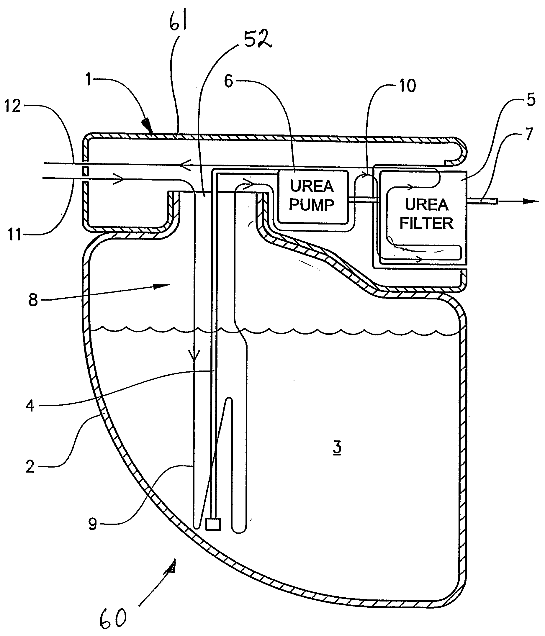
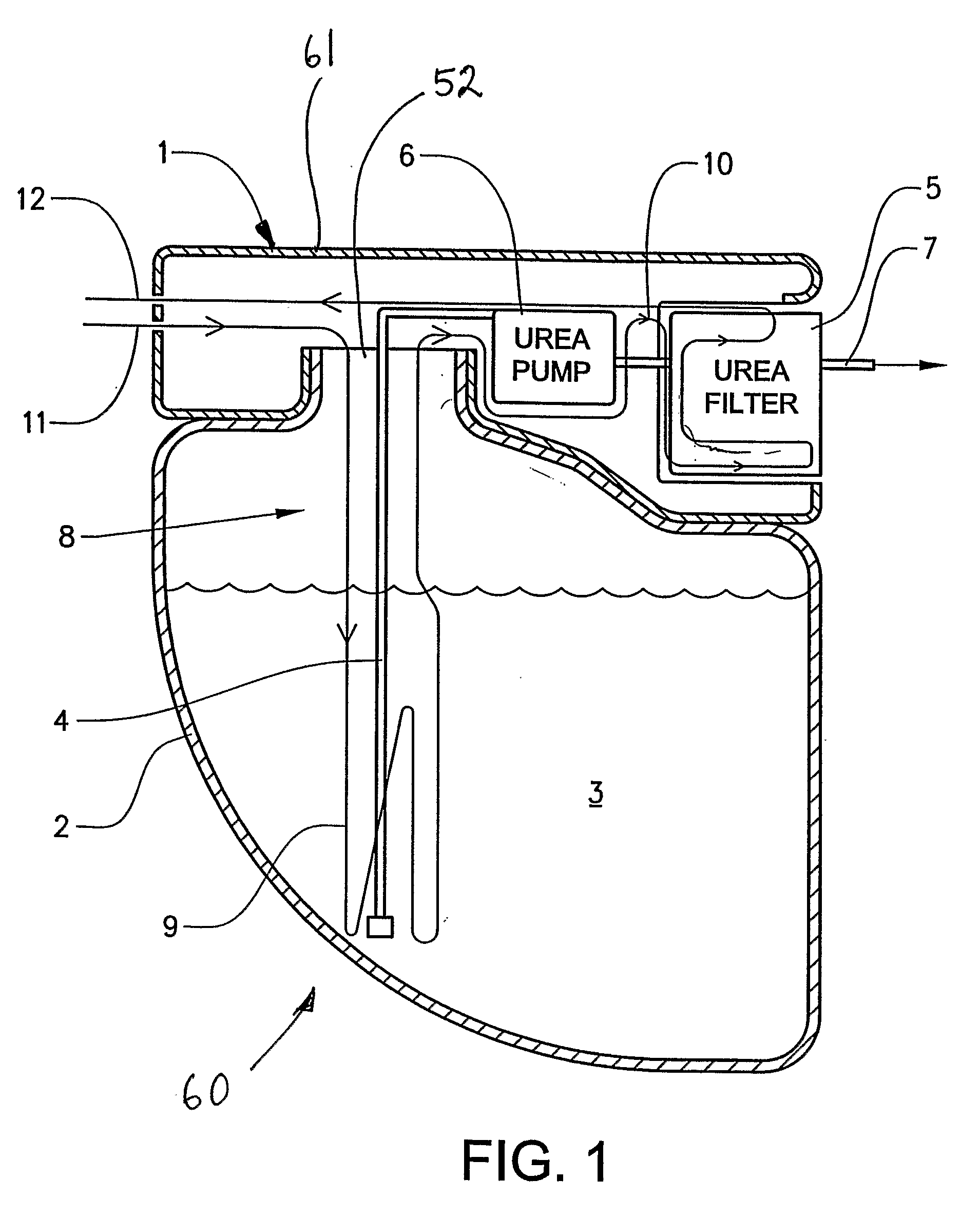
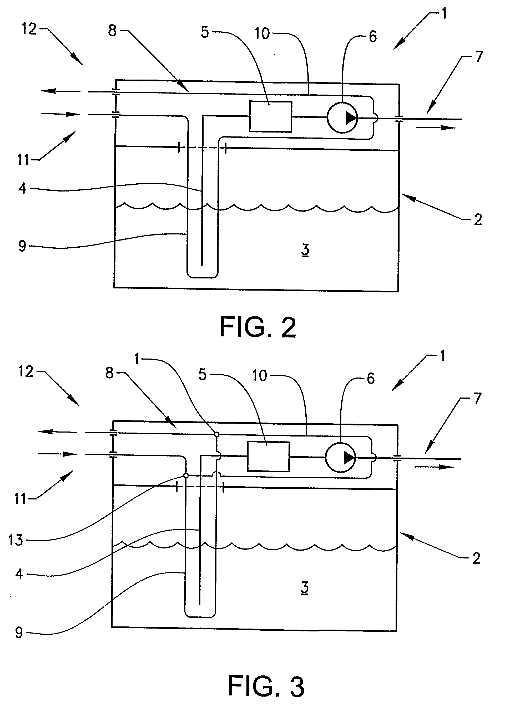
[0025]In FIG. 1 a liquid receptacle 60 for a vehicle according to the invention is schematically illustrated. The liquid receptacle is preferably a tank to be arranged on a vehicle for providing an agent, such as urea, for use in purification of the exhaust of an engine of the vehicle. The liquid receptacle has a first unit 2 with a space for containing a liquid 3 inside the first unit 2 and a second unit 1 which is attached to the first unit 2. The second unit 1 comprises a housing 61 which housing accommodates a pump 6 for conveying liquid out from the first unit 2 and preferably a filter 5 for filtering the liquid to be conveyed so as to remove particles and / or pollutants present in the liquid 3. This filter 5 is arranged downstream the pump.

[0026]Although the term filter 5 is used hereinafter the expression is meant to comprise one or more filters and the filter or filter unit can comprise also a filter holder or the like.

[0027]Although two or more filters are suitably arranged ...


PUM


Abstract

A liquid receptacle for a vehicle includes a first unit having a space for containing a liquid and a second unit which is attached to the first unit. The second unit includes a housing which housing accommodates a pump for conveying liquid out from the first unit and a filter for filtering the liquid to be conveyed.

Description

BACKGROUND AND SUMMARY[0001]The invention relates to a liquid receptacle for a vehicle.[0002]In order to reduce the pollutants contained in the exhaust gas of an internal-combustion engine, in particular the nitrogen oxides, the principle of the regulated or controlled diesel catalytic converter (CDC) has proved advantageous. That procedure is used primarily in internal-combustion engines which are operated with an excess of air, such as, for example, diesel engines and lean-running engines. The procedure, which is based essentially on the method of selective catalytic reduction (SCR) is known. In the case of the SCR method, the nitrogen oxides, together with ammonia, are brought into contact with a selective catalyst and catalytically converted into environmentally safe nitrogen and water.[0003]Due to the danger associated with the use of ammonia, namely the toxicity, and because of the unpleasant smell caused by ammonia, ammonia in its pure form is not carried in the motor vehicle...

Claims


Application Information

Patent Timeline
IPC IPC(8): B65D88/12B60K15/073F01N3/00
CPCF01N3/2066F01N3/36F01N2610/02F01N2610/10Y02T10/24F01N2610/1406F01N2610/1426F01N2610/1486F01N2610/14Y02T10/12Y02A50/20
Inventor MAGNUSSON, MARTINADLERSSON, HANSHENSTROM, BENGTBERNHARDSSON, MAGNUSIVARSSON, ANDERSSONDEREGGER, SIGURDNORDSTROM, HANS
Owner VOLVO LASTVAGNAR AB
Why Eureka
Try Eureka