
Voltage Conversion Device

Inactive Publication Date: 2009-05-21
TOYOTA JIDOSHA KK
View PDF6 Cites 23 Cited by
  • Summary
  • Abstract
  • Description
  • Claims
  • Application Information

AI Technical Summary

Benefits of technology

[0008]An objective of the present invention is to provide a voltage transformer of which the control stability is improved.
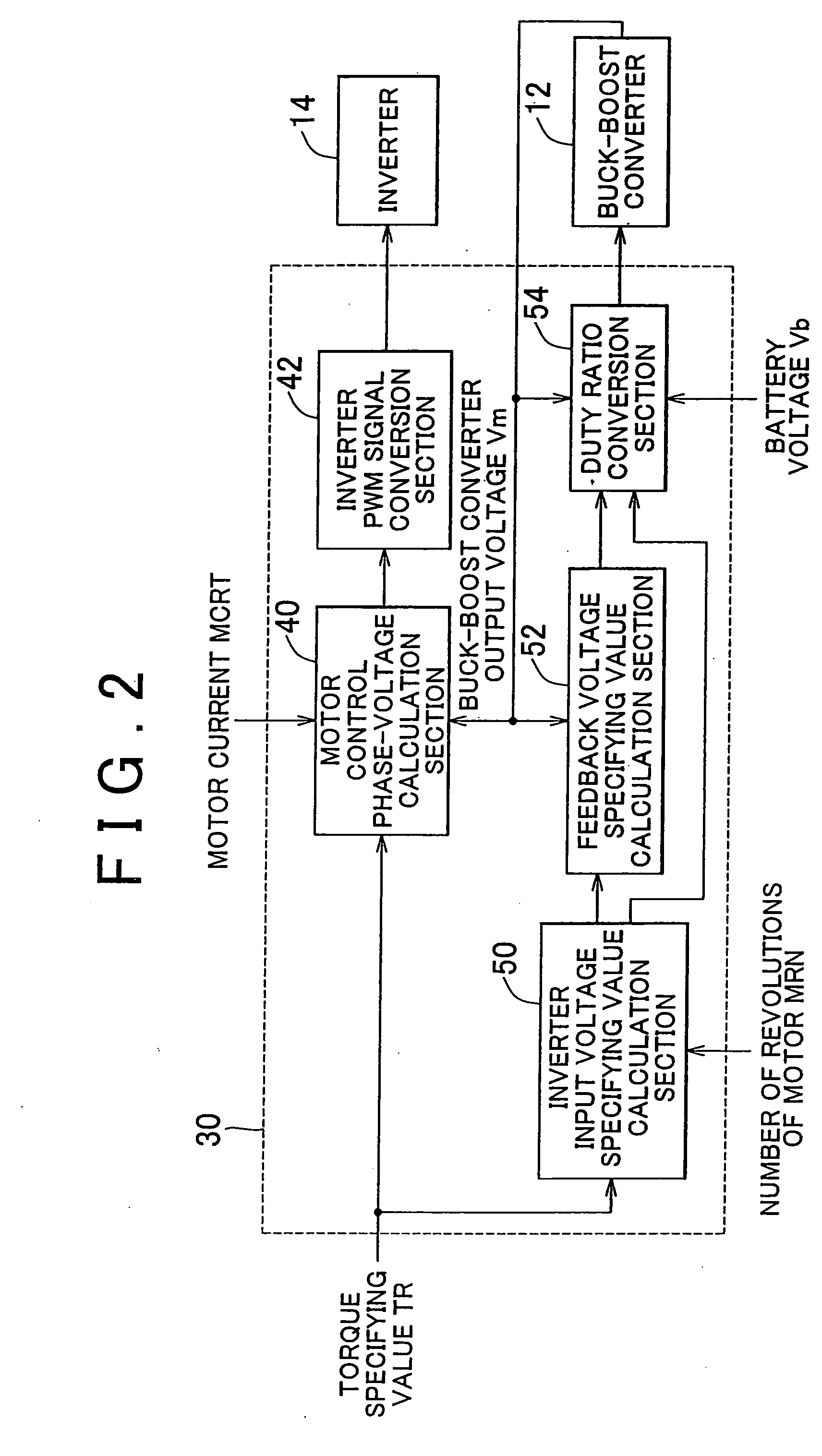
[0010]In the voltage transformer according to the first aspect described above, the controller may perform feedback control of the driver, based on a result of comparing a voltage of the second power line and a desired voltage, and change the operation mode from the rapid operation mode to the slow operation mode by decreasing a value of a feedback gain.
[0014]According to the above aspect of the present invention, the oscillation of electric current and voltage is suppressed, and it is possible to improve the control stability of the voltage transformer.

Problems solved by technology

In such a case, the control stability can be worsened due to the oscillation of the inverter voltage, the battery voltage and the battery current.

Method used


Image

  • Voltage Conversion Device
  • Voltage Conversion Device
  • Voltage Conversion Device

Examples


modified embodiment

[0082]FIG. 7 is a diagram showing the relation between the internal resistance and the temperature of a battery.

[0083]Because the internal resistance of a battery varies with temperature as shown in FIG. 7, it is possible to control the buck-boost converter 12 more stably with changeable feedback gains.

[0084]FIG. 8 is a diagram for explaining an example in which the feedback gain is changed according to the temperature of the battery.

[0085]Referring to FIG. 8, during normal control, the gain Kp is set to 2 when the battery temperature is −15° C. or below, is set to 1.5 when the battery temperature is between −15° C. and −5° C., or is set to 1 when the battery temperature is −5° C. or above. The predetermined value Kp2 used in step S3 of FIG. 4 is set according to the battery temperature in this way.

[0086]On the other hand, while the excessive regeneration is corrected, the gain Kp is set to 1.5 when the battery temperature is −15° C. or below, is set to 1.2 when the battery temperat...


PUM


Abstract

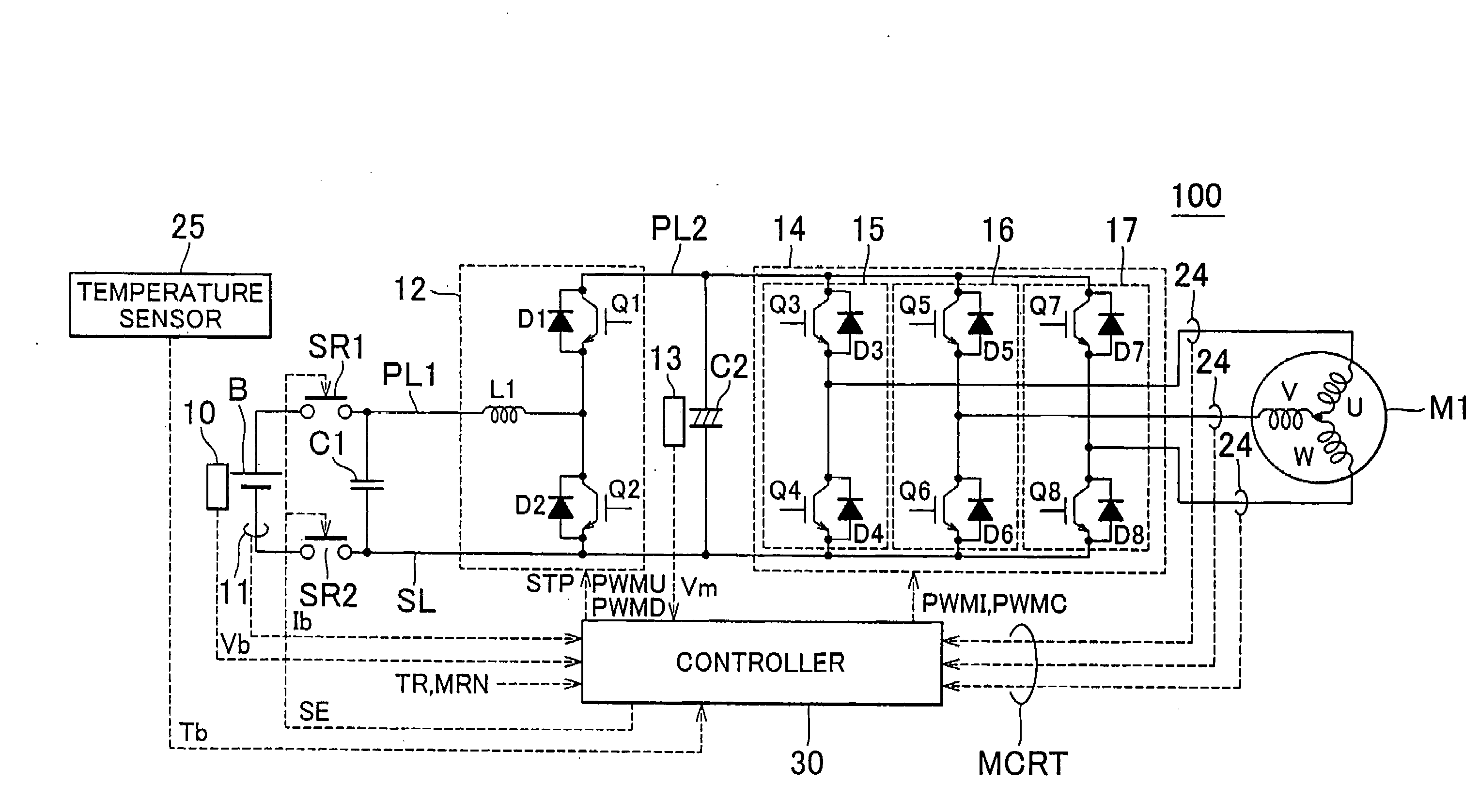
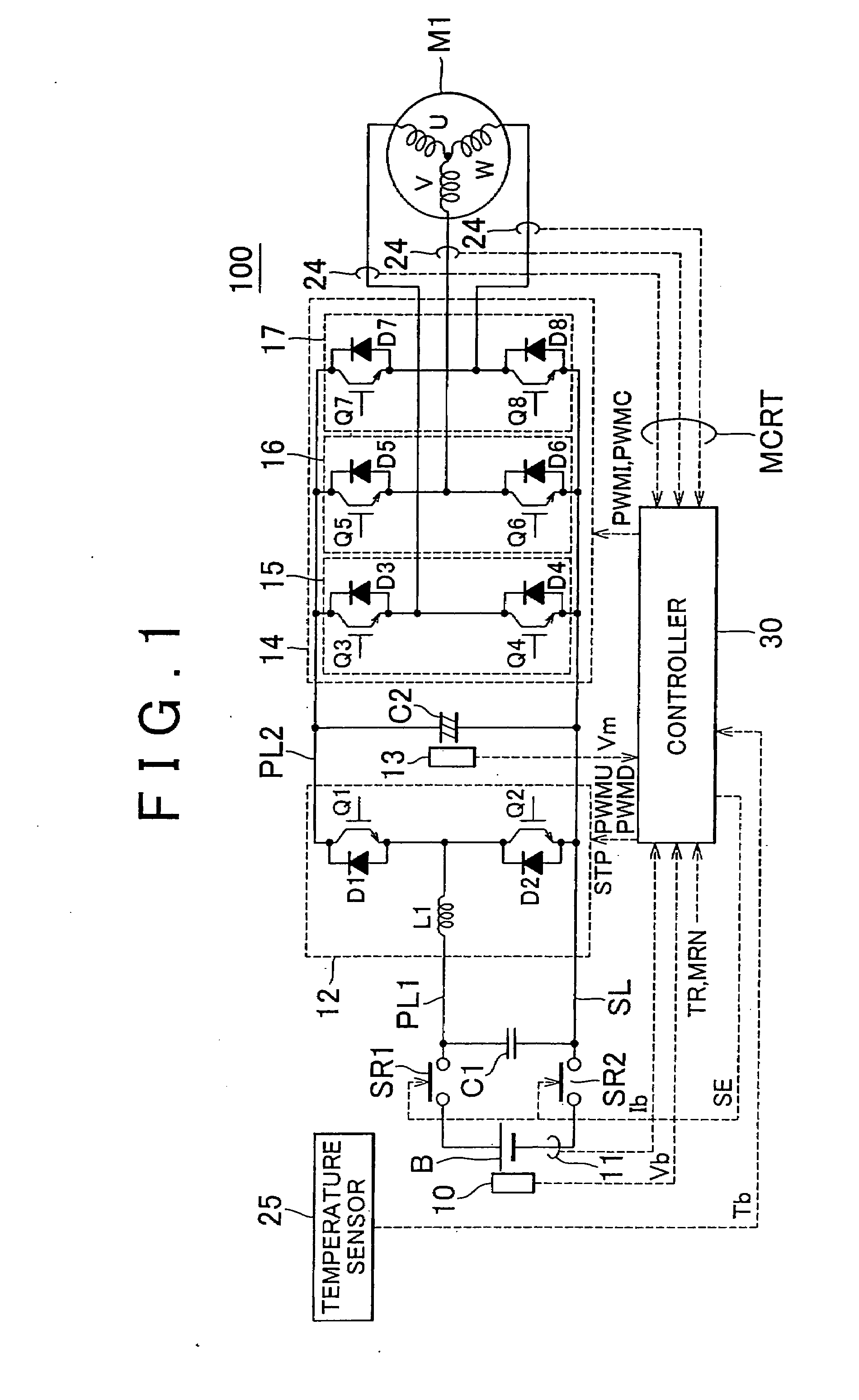
A voltage transformer, which is placed between a DC power source (B) and a motor (M1), includes: a voltage sensor (10) and an electric current sensor (11), which senses input and output of electric power to and from the DC power source (B); a buck-boost converter (12) having power control elements, which is placed in a path connecting between power lines (PL1) and (PL2) that establish the connection to the DC power source (B) and the connection to the motor (M1), respectively; and a controller (30) for controlling the buck-boost converter (12). The controller (30) monitors the change in the regenerated power that is supplied to the DC power source (B), based on the outputs from the voltage sensor (10) and the electric current sensor (11), and, if the amount of change in the regenerated power is greater than a predetermined amount, the controller (30) changes the operation mode of the buck-boost converter (12) from a rapid operation mode to a slow operation mode.

Description

BACKGROUND OF THE INVENTION[0001]1. Field of the Invention[0002]The present invention relates to a voltage transformer for transforming a DC voltage supplied from a DC power source to a desired voltage.[0003]2. Description of the Related Art[0004]In recent years, hybrid vehicles and electric vehicles gain much attention as “green” vehicles.[0005]The hybrid vehicle has a DC power source, an inverter, and a motor that is driven by the inverter, as a driving power source in addition to a conventional engine. Specifically, the hybrid vehicle obtains driving power through the operation of the engine, and by rotating the motor by using the AC voltage that is obtained by converting a DC voltage supplied from the DC power source to the AC voltage via the inverter. The electric vehicle has a DC power source, an inverter, and a motor that is driven by the inverter, as a driving power source.[0006]With regard to the hybrid vehicles and the electric vehicles, it has been studied to boost the DC...

Claims


Application Information

Patent Timeline
IPC IPC(8): G05F5/00H02M3/155H02M7/48
CPCB60L11/1851B60L2210/12B60L2210/14B60L2210/20Y02T10/725Y02T10/7005Y02T10/705Y02T10/7225Y02T10/7233H02M3/1582B60L58/10Y02T10/72Y02T10/70
Inventor OCHIAI, KIYOEOKAMURA, MASAKIYOKOYAMA, SOJIRO
Owner TOYOTA JIDOSHA KK
Learn More