Pupil scan apparatus

a scanning apparatus and pupil technology, applied in the field of pupil scanning apparatus, can solve the problems of double image, inability to achieve stereopsis, eye strain, discomfort, etc., and achieve the effect of less sensitive, high performance and greater efficiency

Active Publication Date: 2009-05-21
ELBIT SYSTEMS OF AMERICA LLC
View PDF17 Cites 77 Cited by
  • Summary
  • Abstract
  • Description
  • Claims
  • Application Information

AI Technical Summary

Benefits of technology

[0071]Currently, full color HUDs in the traditional configuration for avionics applications are impractical for a number of reasons. First, adding the further constraint for color correction strains the ability to provide high performance in other areas, particularly parallax. This issue in isolation could be mitigated by pre-correcting an RGB image on the imaging device such that the projected image is color correct. Second, the brightness of ‘white’ light illumination sources is relatively low and / or inefficient straining the power and waste heat requirements for a HUD. The creation of ‘blue’ is a particular issue as the eye is less sensitive (apparent brightness per optical Watt) and there are few efficient sources of blue light (optical Watts per electrical Watt). Third, the combiner is usually constrained to have a minimum transmission for the look-through scene and must have a minimum of color shift in doing so. For a color HUD this forces either the use of a tremendously expensive, efficient 3-notch (RGB) filter coating, or requires that the illumination system be sufficiently bright to account for the loss of a less expensive, less efficient coating. Because the invention allows for far greater efficiency because only the used portion of the eyebox is illuminated at one time, these issues are mitigated. Because the high speed frame sequential display and correction capability is inherent, correction of the lateral color aberrations can also be performed using an otherwise uncorrected HUD projection optical design.
[0072]In an embodiment, the pupil scanning imager is part of a HUD system wherein the optical relay projects collimated beams to the pupil via a combiner rendering the projected image to appear at infinity and enabling the superposition of the projected image over natural scene transmitted through the combiner. Therein the combiner is part of the optical imaging system. The combiner is a partially reflective and partially transmissive element made so as to reflect a considerable fraction of the incident light beam projecting the image to the observer's pupils yet to transmit a vast fraction of the transmitted light. In an aspect of this embodiment the combiner possesses dioptric power. In another aspect of this embodiment the combiner comprises planar surfaces and is devoid of dioptric power.
[0073]The eye tracker is a standard device used to track pupil location of drivers, pilots and in general personnel whose dynamic eye position is imperative to operating systems such as aircraft, automobiles, trains, military vehicles, to name a few. Some commercial eye trackers operate by emitting and dynamically recording reflected IR radiation from the eye front or back cornea surface. Their bandwidth is typically between 240 and 2000 Hz, well compatible with the pupil scanning imager required bandwidth of about 100 Hz.

Problems solved by technology

In both cases such a projection will result in double images (failure to achieve stereopsis), eyestrain, and / or discomfort.
A further issue results when the apparent location of viewed image points moves as the eyes move laterally in the EMB, meaning that the angle of projection of an object point varies as a function of lateral eye position.
In such cases when this aberration is excessive and because an observer's head and eyes are in constant motion, the image is often interpreted as grossly distorted, disorienting, and ‘swimming’.
All of these negative issues result from parallax errors, an uncorrected difference in the intended angle of light rays from the same object point when projected into different locations in the system exit optical aperture.
For large aperture optics (and therefore low F / Number), correction over the whole aperture presents a challenge.
These measures add cost, complexity, and also tend to increase the physical size as more lenses take up more room.
The requirement for precise parallax correction also limits the ability to implement other potentially desirable attributes such as higher resolution, multicolor projection, and wider fields of view.
If the optical aberration is excessive and because an observer's head and eyes are in constant motion, the image in this case becomes grossly distorted.
The uncorrected difference in the intended angle of light rays emanating from the same object point, when projected into different locations in the system exit aperture, result in parallax errors.
Typically, a biocular HUD optic operates over and requires parallax correction for an F / 0.8 to F / 1.5 relative aperture, which is quite challenging.

Method used


Image

  • Pupil scan apparatus
  • Pupil scan apparatus
  • Pupil scan apparatus

Examples


Embodiment Construction

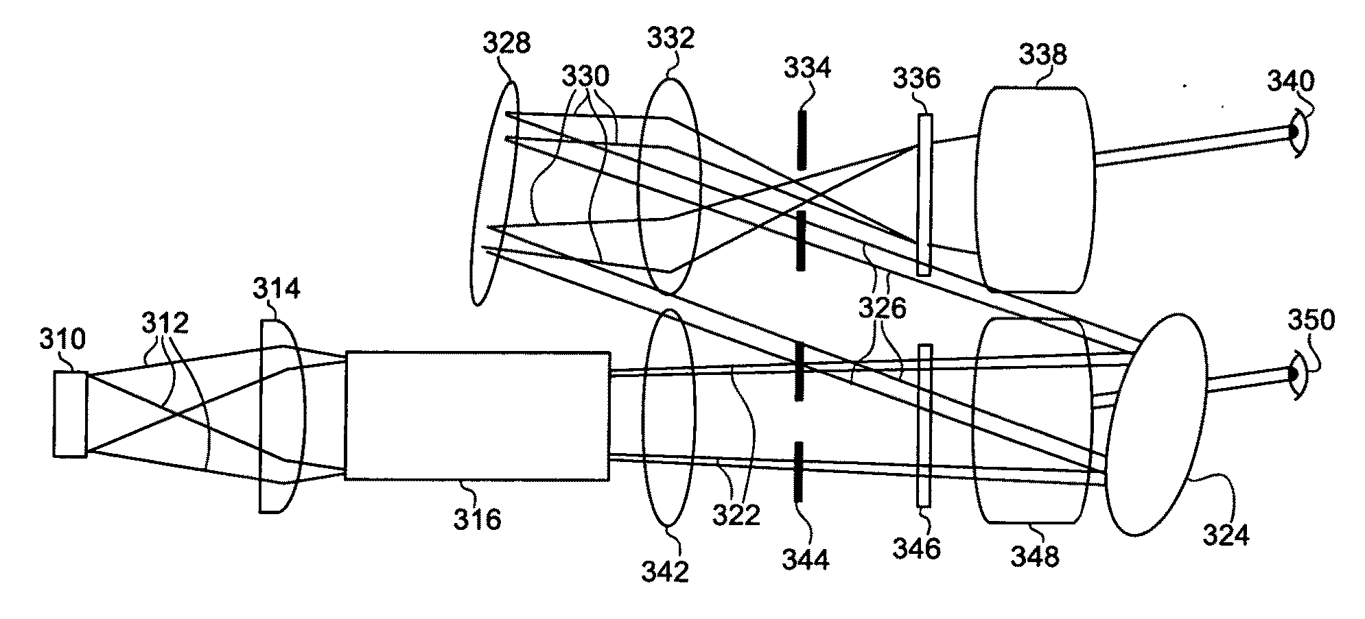
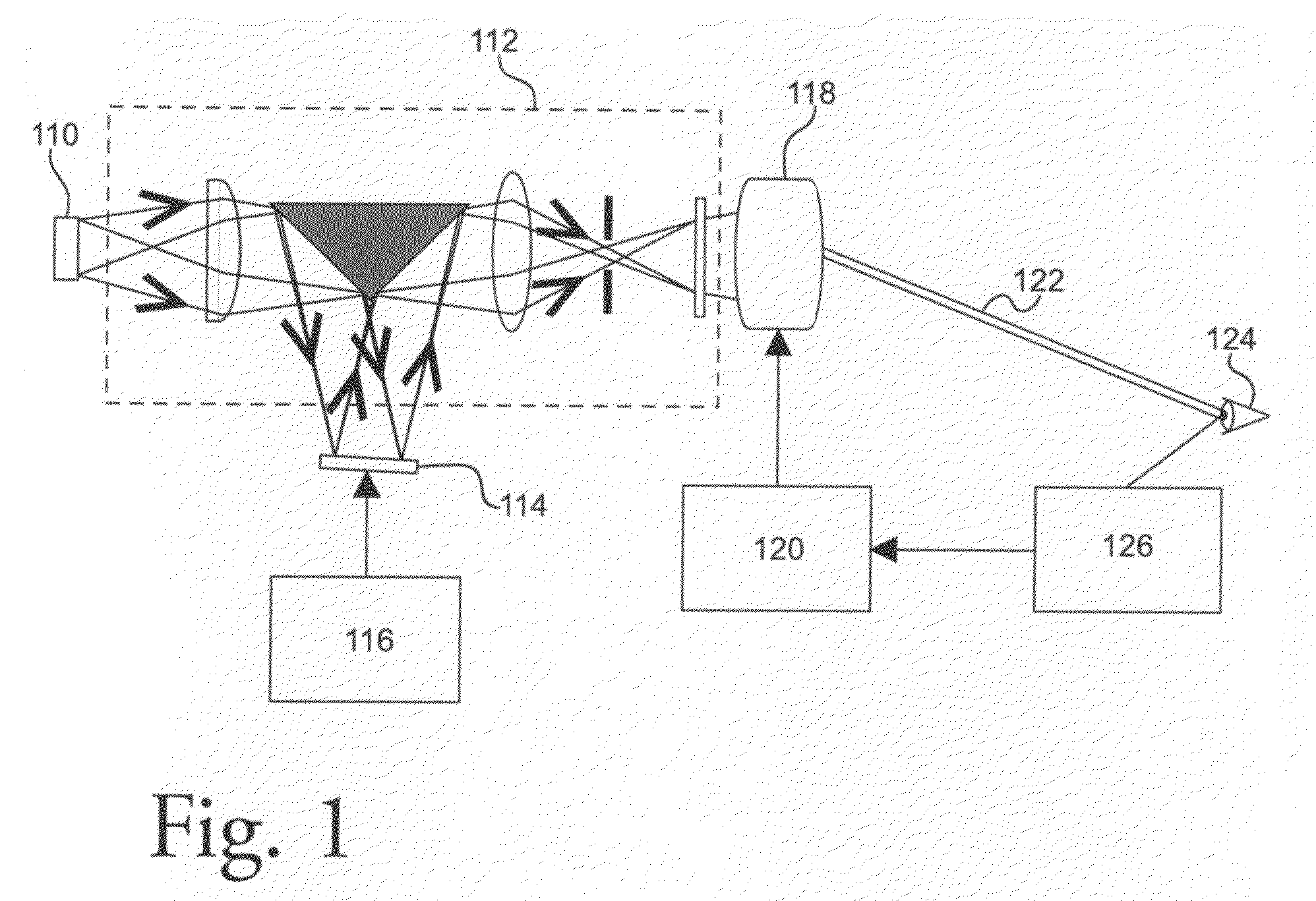
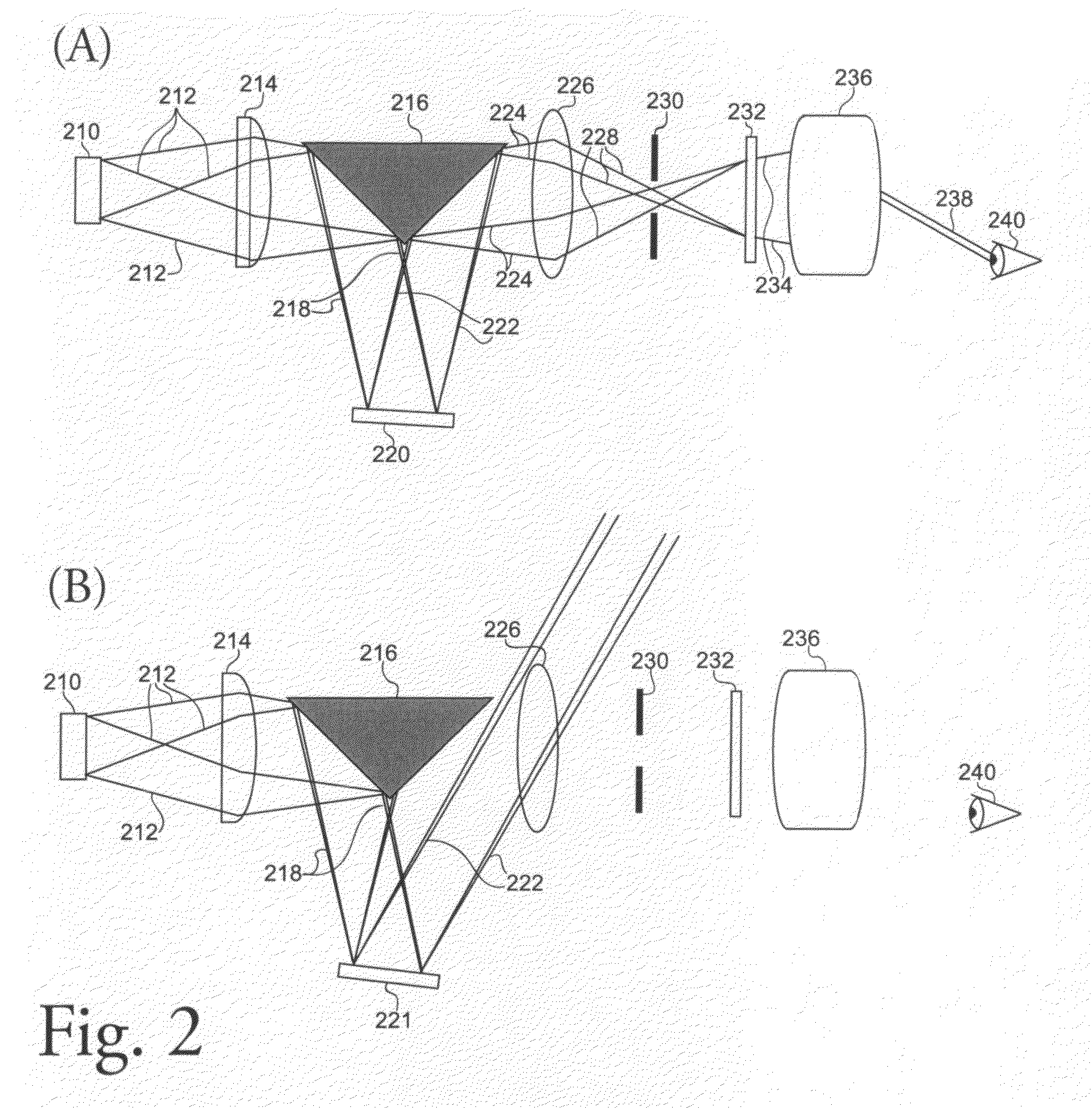
[0051]The invention discloses an apparatus and method by which an image is projected to pupils of an observer preferably covering only areas occupied by the pupils and tracking the areas occupied by the pupils such as to provide continuous display of the imagery to the observer. The method is to dynamically control the direction of light into sub-apertures selected by an eye tracking device. By imaging selectively into the sub-apertures where the eye pupils are temporally located instead of imaging into a generally large area the disclosed apparatus is power efficient and exclusive because the projected images are covert. This method is applicable to most biocular displays, for instance but not limited to “see through” systems, which overlay imagery over real world scenes and where geometrically precise projection is critical.

[0052]Human eye pupils have a diameter varying between 4 and 7 mm, depending on the magnitude of background light, direct illumination and psychological-physio...


PUM


Abstract

An apparatus and method by which an image is projected to pupils of a viewer. Preferably, the image covers only areas occupied by the pupils and tracks the areas occupied by the pupils such as to provide continuous display of the imagery to a viewer. The method is to dynamically control the direction of light into sub-apertures selected by a tracking device. By imaging selectively into the sub-apertures where the pupils are temporally located instead of imaging into a generally large area, the disclosed apparatus is power efficient and exclusive because the projected images are covert. This method is applicable to most biocular displays, for instance, but not limited to “see through” systems, which overlay imagery over real world scenes and where geometrically precise projection is critical. In one embodiment, the pupil scan apparatus is combined with a retinal scan apparatus to provide security. In this manner, only an authorized user of the apparatus can operate it.

Description

[0001]This application claims benefit of U.S. Provisional Application Ser. No. 60 / 998,143, filed Oct. 9, 2007, pursuant to 35 USC §119(e).FIELD OF INVENTION[0002]A pupil scanning apparatus to dynamically project images into selected sub-apertures of a biocular display optical system.BACKGROUND OF THE INVENTION[0003]The design of biocular optics for projected displays must take into account a variety of factors to display the image as desired. It must be color corrected for the desired wavelengths, must maintain imaging and brightness performance over its entire eye motion box (EMB), and when both eyes are in the exit aperture, it must have the specified level of parallax between the left and right eye images.[0004]Biocular displays are typically designed to project a single object as a stereoscopic image pair, which will appear from a defined apparent distance. When the angles of incidence at the observer's eyes are parallel between the left and right eyes, the image will appear to ...

Claims


Application Information

Patent Timeline
Patent Type & Authority Applications(United States)
IPC IPC(8): G02B27/22G03B21/00G02B27/01
CPCG02B13/22G02B26/10G02B2027/014G02B27/2228G02B2027/0134G02B27/01G02B30/34
Inventor TILLEMAN, MICHAEL M.EVERETT, JONATHANWOLFE, RICHARD
Owner ELBIT SYSTEMS OF AMERICA LLC
Why Eureka
Try Eureka