Method for controlling a pump arrangement, and pump arrangement

a technology of pump arrangement and control mechanism, which is applied in the direction of machines/engines, positive displacement liquid engines, lighting and heating apparatus, etc., can solve the problems of only minimal pump operation, undesired fluctuations of pressure and flow rate in the delivered product, and delay the delivery of substitute pumps to achieve the desired delivery, etc., to achieve the effect of reducing hydraulic braking torque, facilitating acceleration to the target rotational speed, and reducing volume flow

Inactive Publication Date: 2009-05-21
LINDE AG
View PDF0 Cites 15 Cited by
  • Summary
  • Abstract
  • Description
  • Claims
  • Application Information

AI Technical Summary

Benefits of technology

[0008]For example, a control line as close as possible to the cavitation boundary can be defined for the operating point of the pump, which results in a favourable reduction of the volume flow which, in turn, rules out the possibility of cavitation occurring.
[0011]Reducing the volume flow leads to a lower hydraulic braking torque, which facilitates acceleration to the target rotational speed. This indirectly minimizes the hydraulic braking torque during the power-up phase.
[0022]The pump arrangement can comprise a cavitation limit control device which controls the bypass valve as a function of the current volume flow through the pump and a current rotational speed of the pump drive of the pump. A closed-loop control can also be effected as a function of the pressure difference between input and output sides, the current rotational speed and / or the delivery height. The cavitation limit control device is provided as otherwise damage due to cavitation may occur, in particular with cryogenic fluids. Moreover, a pressure controller recording the outlet pressure can be provided, which controls the bypass valve so that a predetermined maximum outlet pressure is not exceeded. However, control by the cavitation limit control device should have priority.

Problems solved by technology

So-called “slow-roll” operating modes are known for such substitute pumps, with the drive motor being active, the pump performs, however, only minimal delivery work.
However, especially during the power-up phase, a corresponding pump drive does not always develop its peak torque, which delays the substitute pump's achieving its desired delivery result.
Thus, undesired fluctuations of pressure and flow rate may occur in the delivered product at the pump output.

Method used


Image

  • Method for controlling a pump arrangement, and pump arrangement
  • Method for controlling a pump arrangement, and pump arrangement
  • Method for controlling a pump arrangement, and pump arrangement

Examples


Embodiment Construction

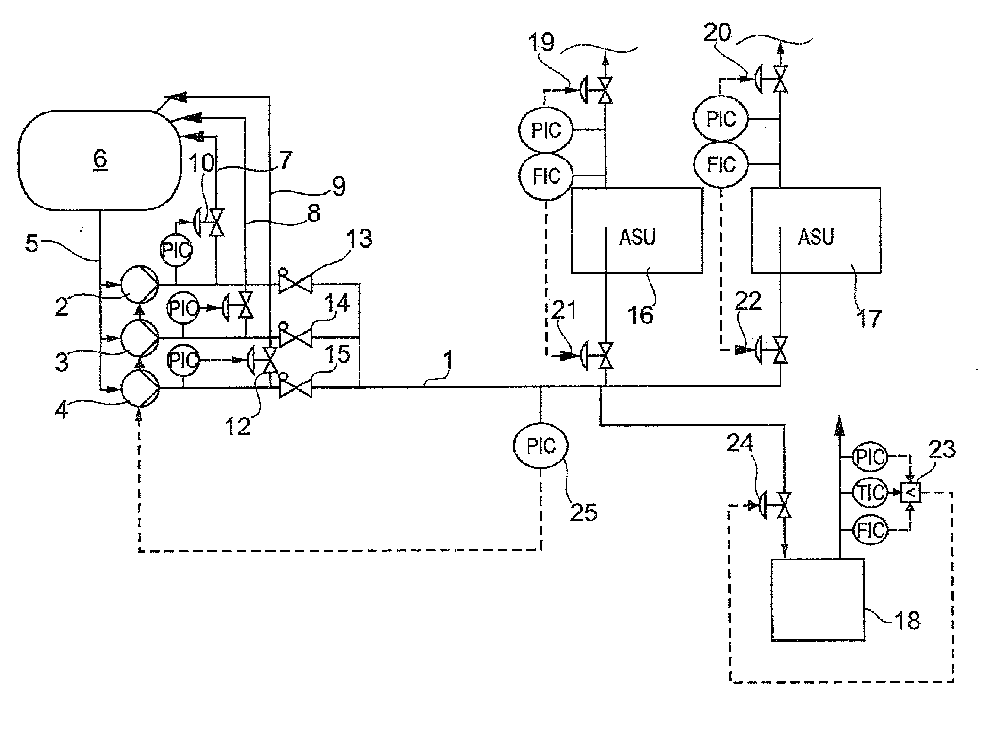
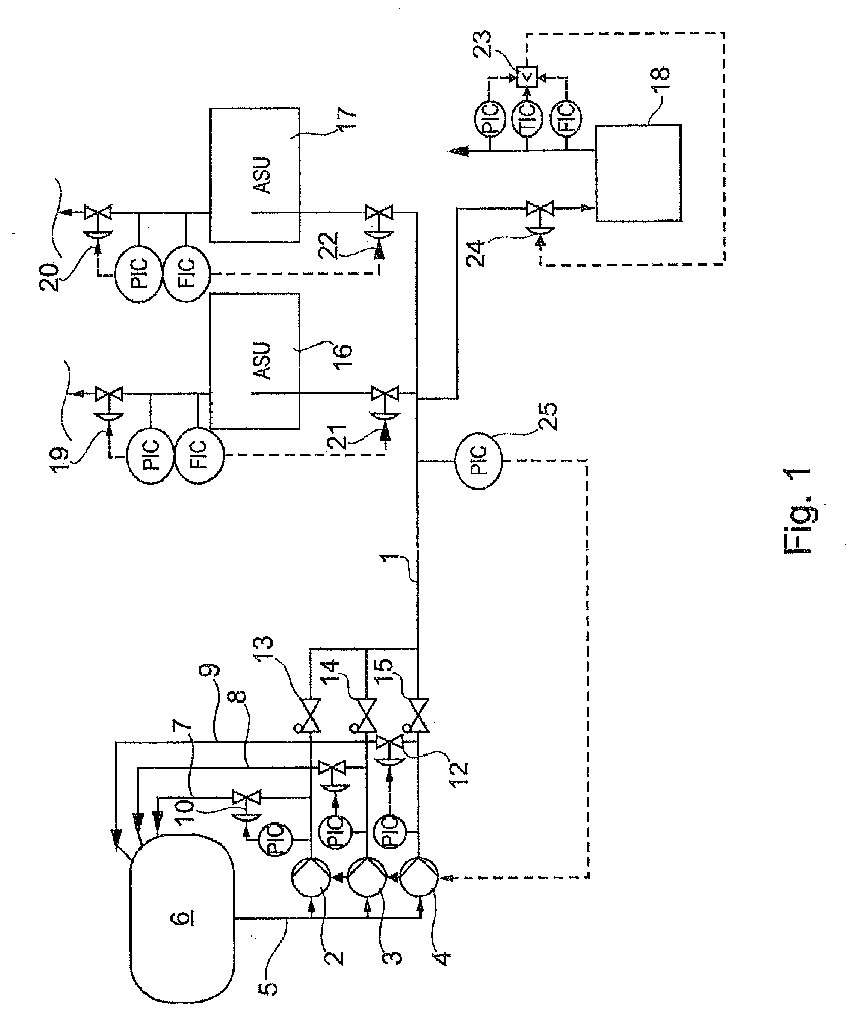
[0030]In air separation units with internal compression, for example, cryogenic air or liquids (LIN, LOX, LAR=liquid nitrogen, oxygen, argon) are brought to an operating pressure by pumping or delivery, and are routed to a heat exchanger of the air separation unit (ASU) in question within which the corresponding cryogenic liquid is evaporated. In order to enable the respective process to be continued in case of failure of one of the pumps, redundant pumps are provided as substitute pumps in the case of failure of the working pump, properly speaking. It is also conceivable that several individual plant components are supplied with pressurized cryogenic liquid from a common reservoir or tank. This is represented schematically in FIG. 1, for example.

[0031]A common high-pressure liquid line 1 is provided, which is supplied with high-pressure liquid by the three pumps 2, 3, 4. The pumps are supplied with the corresponding product via a supply line 5 from a joint reservoir or tank 6. For ...


PUM


Abstract

A method for controlling a pump arrangement comprising a fluid delivering pump having a pump drive, a bypass line having a bypass valve for routing fluid back from an outlet side of the pump to a reservoir is disclosed. During ramping up the pump drive to a predetermined target rotational speed, the bypass valve is controlled to reduce a volume flow through the pump so that the volume flow, at a respective delivery height, lies between a cavitational volume flow and the cavitational volume flow increased by a predetermined maximum volume flow deviation.

Description

BACKGROUND OF THE INVENTION[0001]The present invention relates to a method for controlling a pump arrangement which is used, for example, in cryotechnical plants. The invention further relates to an arrangement comprising one or more pumps for providing pressurized cryogenic liquid, the arrangement being suitable, for example, for use in an air liquefaction plant.[0002]Open-loop and closed-loop control of pump drives to predetermined target values such as a desired output pressure, as a function of various measurable values, for example a pressure difference between pump inlet and pump outlet, volume flows or mass flow rates, a rotational speed of the pump drive or similar values, is necessary particularly in large-scale fluid-processing plants. The use of three-phase asynchronous motors as pump drives is common in this context. Cryogenic pumps, i.e. pumps which deliver cryogenic liquids at temperatures lower than −170° C., are operated by corresponding three-phase asynchronous mach...

Claims


Application Information

Patent Timeline
Patent Type & Authority Applications(United States)
IPC IPC(8): F04B49/24F04B49/00F25J3/00
CPCF04B15/08F25J2290/62F04B2203/0209F04B2205/05F25J3/04084F25J3/0409F25J3/04096F25J3/04781F25J3/04787F25J3/04818F25J3/04824F25J3/04963F25J2230/22F25J2235/02F25J2245/02F25J2290/10F04B23/04
Inventor HAAS, SEBASTIAN
Owner LINDE AG
Why Eureka
Try Eureka