Desiccant sealing arrangement for OLED devices

a technology of sealing arrangement and oled device, which is applied in the manufacture of electrode systems, semiconductor devices, electric discharge tubes/lamps, etc., can solve the problems of low level achievable, low moisture capacity of molecular sieve materials, and inability to so as to improve the ease of manufacture, reduce the moisture level inside oled devices, and reduce the cost

Active Publication Date: 2009-05-21
GLOBAL OLED TECH
View PDF46 Cites 25 Cited by
  • Summary
  • Abstract
  • Description
  • Claims
  • Application Information

AI Technical Summary

Benefits of technology

[0017]It is therefore an object of the present invention to reduce the permeability of moisture into an OLED device. It is a further object of this invention to provide the reduced moisture permeability with a minimum non-emitting area on the OLED device. It is a further object of this invention to protect an OLED device from any moisture that penetrates the sealed region containing the OLED device.
[0024]It is an advantage of this invention that it reduces the level of moisture inside OLED devices and the permeability of moisture into such devices. It is a further advantage of this invention that it can do this while relying less on highly active desiccants, thus improving ease of manufacture and reducing cost. It is a further advantage of this invention that OLED displays can be formed without the need of completely hermetic seals. It is a further advantage of this invention that it protects OLED devices from moisture that penetrates the sealed region containing the OLED device. It is a further advantage of this invention that OLED displays with a large capacity for moisture can be made without increasing the display size to accommodate the desiccant.

Problems solved by technology

A common problem with OLED displays is sensitivity to moisture.
Such low levels are not achievable with desiccants of silica gel materials and of Drierite materials.
However, molecular sieve materials have a relatively low moisture capacity at humidity levels at or below 1000 ppm, requiring large quantities of desiccant when used in the standard methods of the prior art.
Because space within the standard enclosure is typically limited to minimize the area and / or depth of the enclosure, low capacity desiccants are typically not used, even when these desiccants have the desirable feature of fast water absorption.
However, even when finely divided into powders of 0.2 to 200 μm particle size, such materials often chemically absorb moisture relatively slowly compared to the above-mentioned molecular sieve, silica gel, or Drierite materials.
Such relatively slow reaction with water vapor can lead to a measurable degree of performance degradation if the rate of moisture permeating through the seal between the device and the cover exceeds the rate of water absorption by the desiccant.
The requirement that the desiccating agents of the prior art not be reactive toward the layers and electrodes of OLED devices and the requirement to keep the desiccating agents from contacting the OLED components limits the choices of possible desiccating agents.
These limitations can require very wide seals, and thus wide borders beyond the display area, to prevent the rate of moisture permeation from exceeding the rate of moisture absorption by the desiccating agents.
For top emitting OLED devices in particular, this enclosure size requirement can be a significant issue since most desiccating agents are not transparent, and therefore cannot be located over the emitting areas of the OLED.
For top emitting OLED devices, desiccating agents must typically be placed outside the display area, but still inside the enclosure, resulting in large borders beyond the display area.
Therefore, it is possible that the properties of the optical path of the device will change during the device lifetime, leading to potential visual changes in the display.
This can limit the usefulness of this method.
However, many of the desiccants disclosed by Shores will not function effectively with highly moisture-sensitive devices at a humidity level lower than 1000 ppm.
Similarly, binders, such as polyethylene disclosed by Shores, which have low moisture absorption rates compared to the absorption rate of the pure selected desiccants, would not function effectively to achieve and to maintain a humidity level below 1000 ppm during a projected operational lifetime of a highly moisture-sensitive device.
None of these desiccants, other than zeolite, will function effectively with highly moisture-sensitive devices at a humidity level lower than 1000 ppm, and zeolite has the problem described above of low capacity at humidity levels lower than 1000 ppm.
In addition the moisture vapor transmission rate requirement for the resin is not adequately defined since there is no reference to the thickness of the measured resins.
It is therefore not possible to determine if the moisture vapor transmission rates disclosed by Deffeyes are sufficient for highly moisture-sensitive devices.
Booe does not teach the impact of particle size on desiccant performance.
Attempts at this in the art have been less than satisfactory.
While this can be a way to reduce the likelihood of sealant failure, it is no more effective at reducing moisture transmission rate into the device than would be a single wider sealant.
This can reduce the moisture transmission rate into the device, but does not protect the OLED device from moisture sealed into the enclosure initially nor from moisture that permeates the inner seal.
In addition, Wang et al. require the use of ribs that must be formed between the seals in order to hold the desiccant, adding complexity and expense to the fabrication process.
However, Peng requires the use of a separate sealing ring to hold the desiccant, adding extra steps and complexity to the fabrication process.
Peng also fails to provide protection for the OLED devices from moisture that penetrates the interior seal.
Rogers fails to recognize the criticality of including an actual desiccant both between the adhesive rings and within the enclosure containing the OLED device.
With no desiccant within the enclosure containing the OLED device, the OLED device is not protected from moisture sealed initially within the enclosure, nor from moisture that permeates the inner adhesive ring.
The method described, however, does not address the problem of high moisture permeation rates that can exceed the rate of moisture absorption by the desiccant.
Because the first and second chambers are in direct vapor communication, the seal of the first chamber does not provide any additional resistance to moisture permeation beyond a traditional single seal.

Method used


Image

  • Desiccant sealing arrangement for OLED devices
  • Desiccant sealing arrangement for OLED devices
  • Desiccant sealing arrangement for OLED devices

Examples


Embodiment Construction

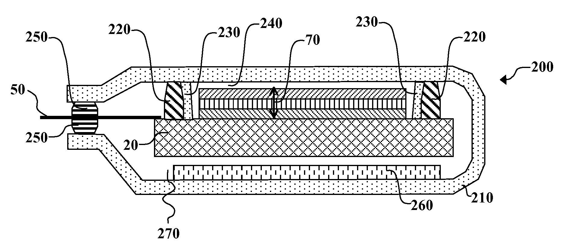
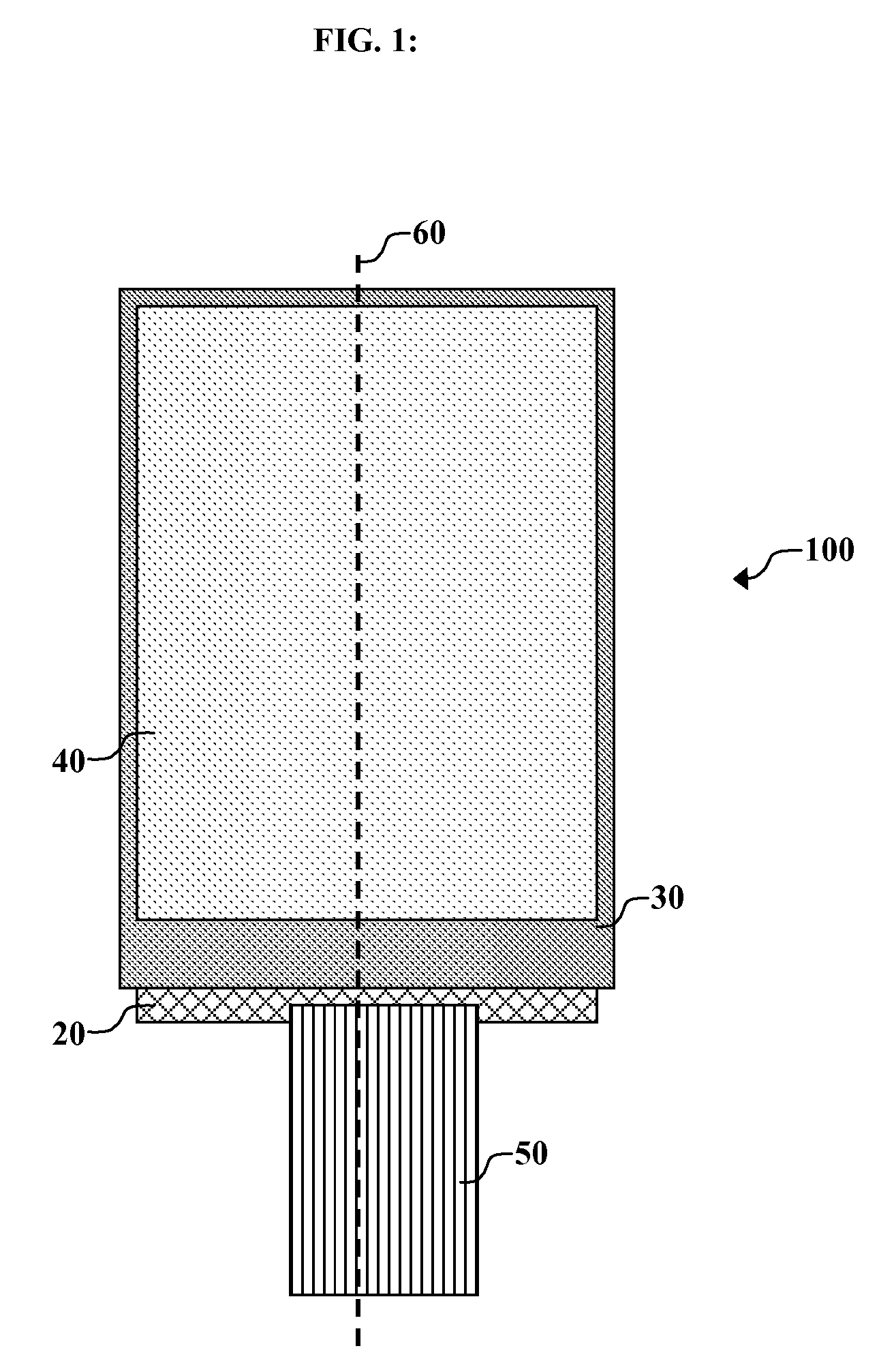
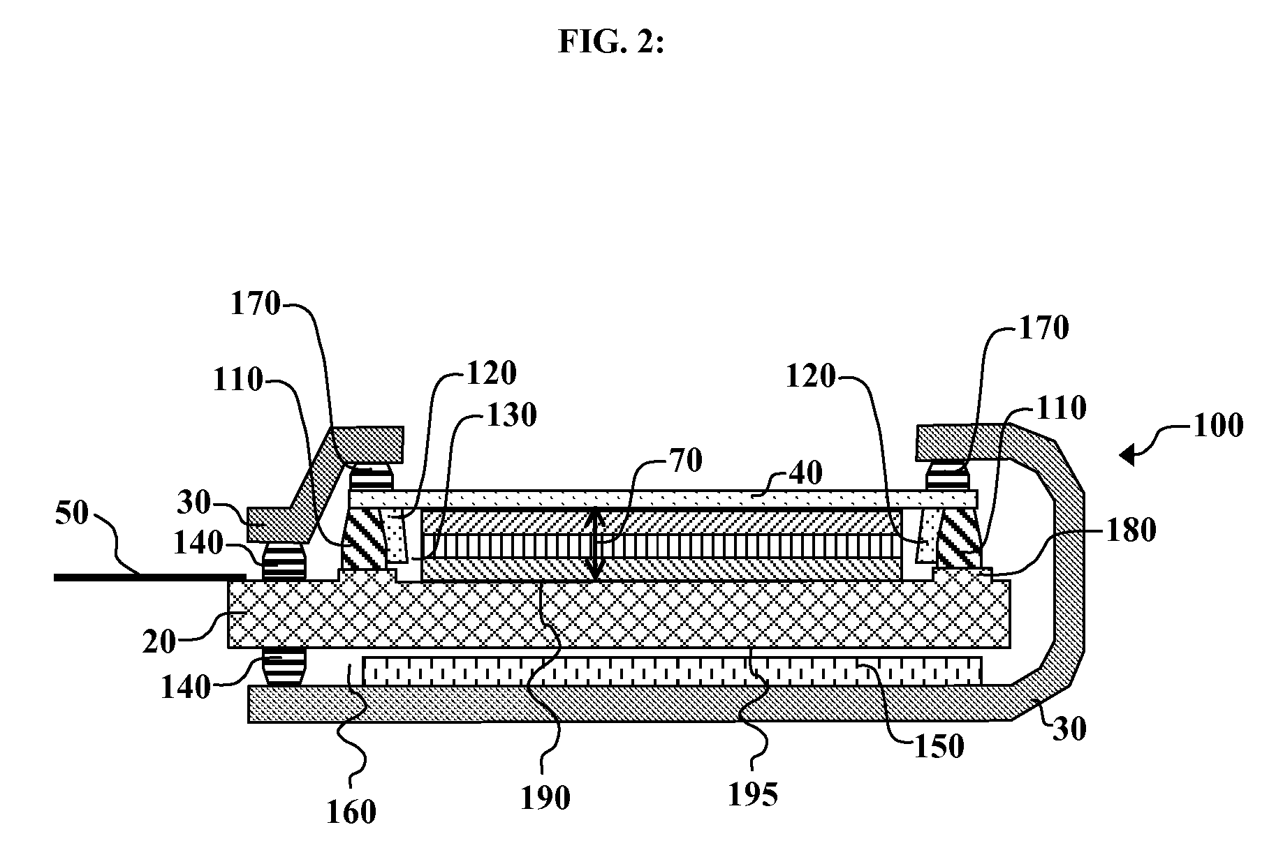
[0030]The term “OLED device” or “organic light-emitting display” is used in its art-recognized meaning of a display device comprising organic light-emitting diodes as pixels. The term “top-emitting” refers to display devices in which light is primarily not emitted through the substrate upon which they are based but opposite to the substrate, and are viewed through the side opposite to the substrate. The term “highly moisture-sensitive electronic device” is employed to designate any electronic device that is susceptible to a measurable degradation of device performance at ambient moisture levels greater than 1000 ppm. The term “substrate” is employed to designate organic, inorganic, or combination organic and inorganic solids on which one or more highly moisture-sensitive electronic devices are fabricated. The term “sealing material” is employed to designate organic, inorganic, or combination organic and inorganic materials used to bond encapsulation enclosures to substrates and to p...


PUM


Abstract

A method of encapsulating an OLED device includes forming an OLED device on a substrate; providing a protective cover surrounding the OLED device and the substrate; providing a first sealing arrangement between the protective cover and top surface of the substrate, to define a first chamber enclosing the OLED device; providing a second sealing arrangement sealed to define a second chamber sealed from and enclosing the first chamber; and providing first desiccant material in the first chamber and providing second desiccant material in the second chamber closer to the bottom surface of the substrate than the top surface.

Description

CROSS REFERENCE TO RELATED APPLICATION[0001]Reference is made to commonly assigned U.S. patent application Ser. No. 11 / 336,539 filed Jan. 20, 2006 (published as U.S. Published Patent Application No. 2007 / 0172971) entitled “Desiccant Sealing Arrangement for OLED Devices” by Michael L. Boroson; the disclosure of which is incorporated herein by reference.FIELD OF THE INVENTION[0002]The present invention relates to protecting OLED devices from moisture.BACKGROUND OF THE INVENTION[0003]An organic light-emitting diode device, also called an OLED device, commonly includes a substrate, an anode, a hole-transporting layer made of an organic compound, an organic luminescent layer with suitable dopants, an organic electron-transporting layer, and a cathode. OLED devices are attractive because of their low driving voltage, high luminance, wide-angle viewing, and capability for full-color flat emission displays. Tang et al. described this multilayer OLED device in their U.S. Pat. Nos. 4,769,292 ...

Claims


Application Information

Patent Timeline
Patent Type & Authority Applications(United States)
IPC IPC(8): H01J9/26
CPCH01L2251/5315H01L51/5237H10K50/846H10K50/841H10K50/8426H10K50/84H10K2102/3026
Inventor BOROSON, MICHAEL L.HAMER, JOHN W.
Owner GLOBAL OLED TECH
Why Eureka
Try Eureka