Systems and methods for deploying echogenic components in ultrasonic imaging fields

a technology of ultrasonic imaging and components, applied in the field of medical systems and methods, can solve the problems of difficult visualization, limited advantages, difficult to accurately image and track the distal tip of the needle, etc., and achieve the effect of enhancing the image of the needle and facilitating the follow-up of the progress

Inactive Publication Date: 2009-05-21
GYNESONICS
View PDF2 Cites 52 Cited by
  • Summary
  • Abstract
  • Description
  • Claims
  • Application Information

AI Technical Summary

Benefits of technology

[0007]The present invention provides both apparatus and methods for visualizing and treating target tissue regions in a patient. The apparatus comprises a shaft or other support which carries an ultrasound imaging transducer or transducer array (referred to herein as “transducer”), typically at or near its distal end. The ultrasound imaging transducer provides imaging within a field of view, typically extending laterally from an axis of the shaft. An elongate component is deployable from the shaft within the field of view so that the component may be imaged as it is advanced through the field of view. In accordance with the principles of the present invention, the component will be modified to have an artifact thereon which is configured to preferentially reflect at least a portion of the ultrasound energy emanating from the ultrasound transducer back to the transducer. In this way, the image of the needle will be enhanced so that it is easier to follow the progress of the needle as it is deployed from the shaft, typically into the tissue being treated.

Problems solved by technology

Such visualization may be difficult, however, particularly if the needle has turned away from the field of view.
The advantages are limited somewhat, however, because it is difficult to accurately image and track the distal tip of the needle as it turns in a direction perpendicular to the transducer which is generally parallel to the field of view.

Method used


Image

  • Systems and methods for deploying echogenic components in ultrasonic imaging fields
  • Systems and methods for deploying echogenic components in ultrasonic imaging fields
  • Systems and methods for deploying echogenic components in ultrasonic imaging fields

Examples


Embodiment Construction

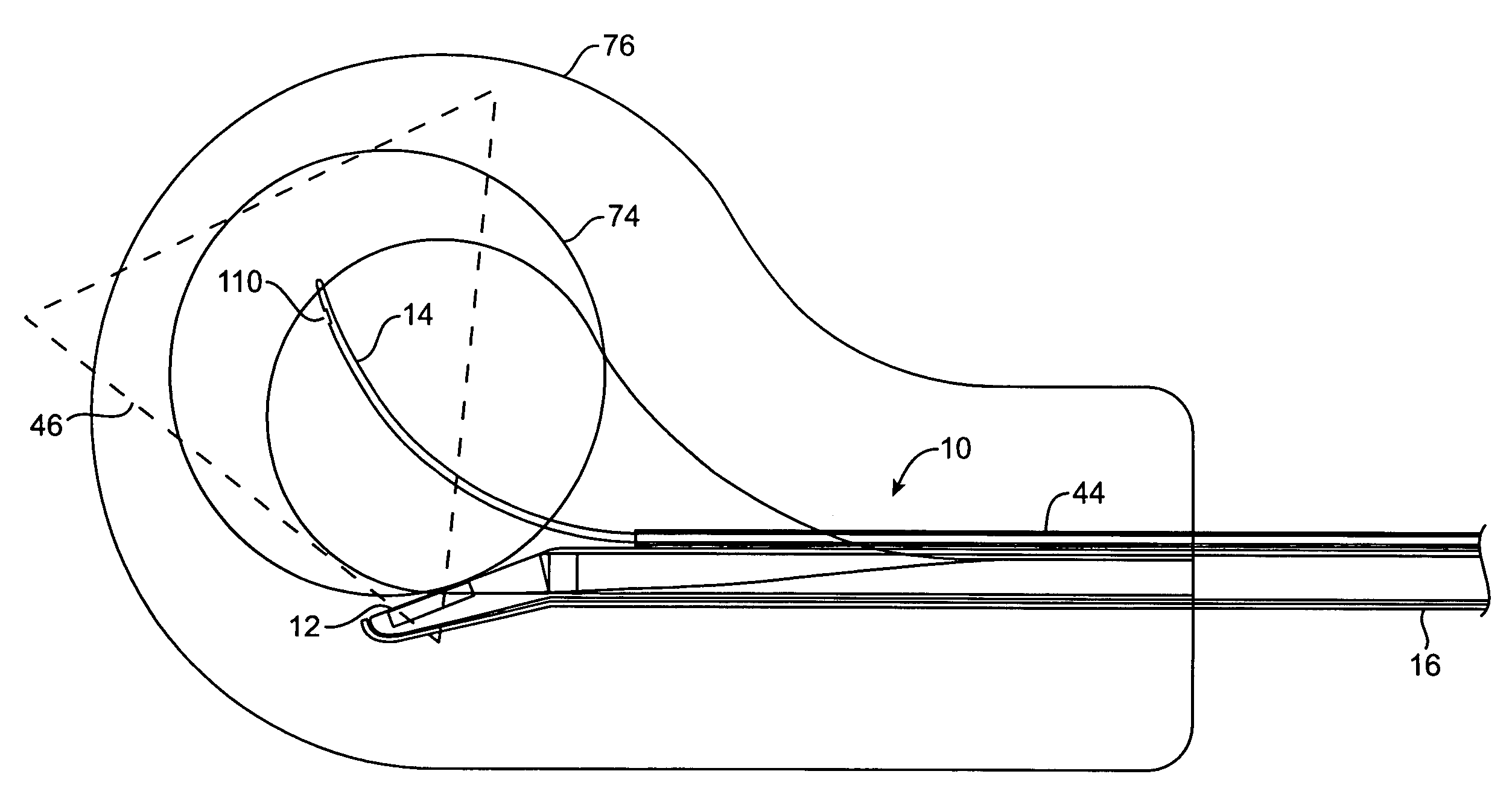
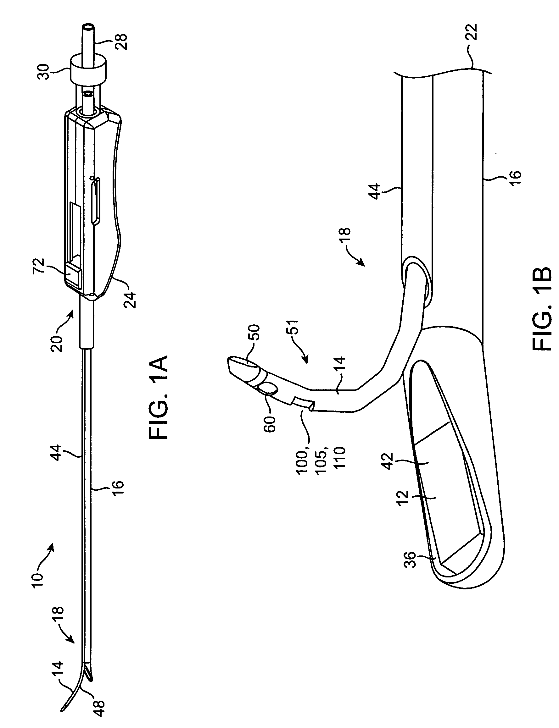
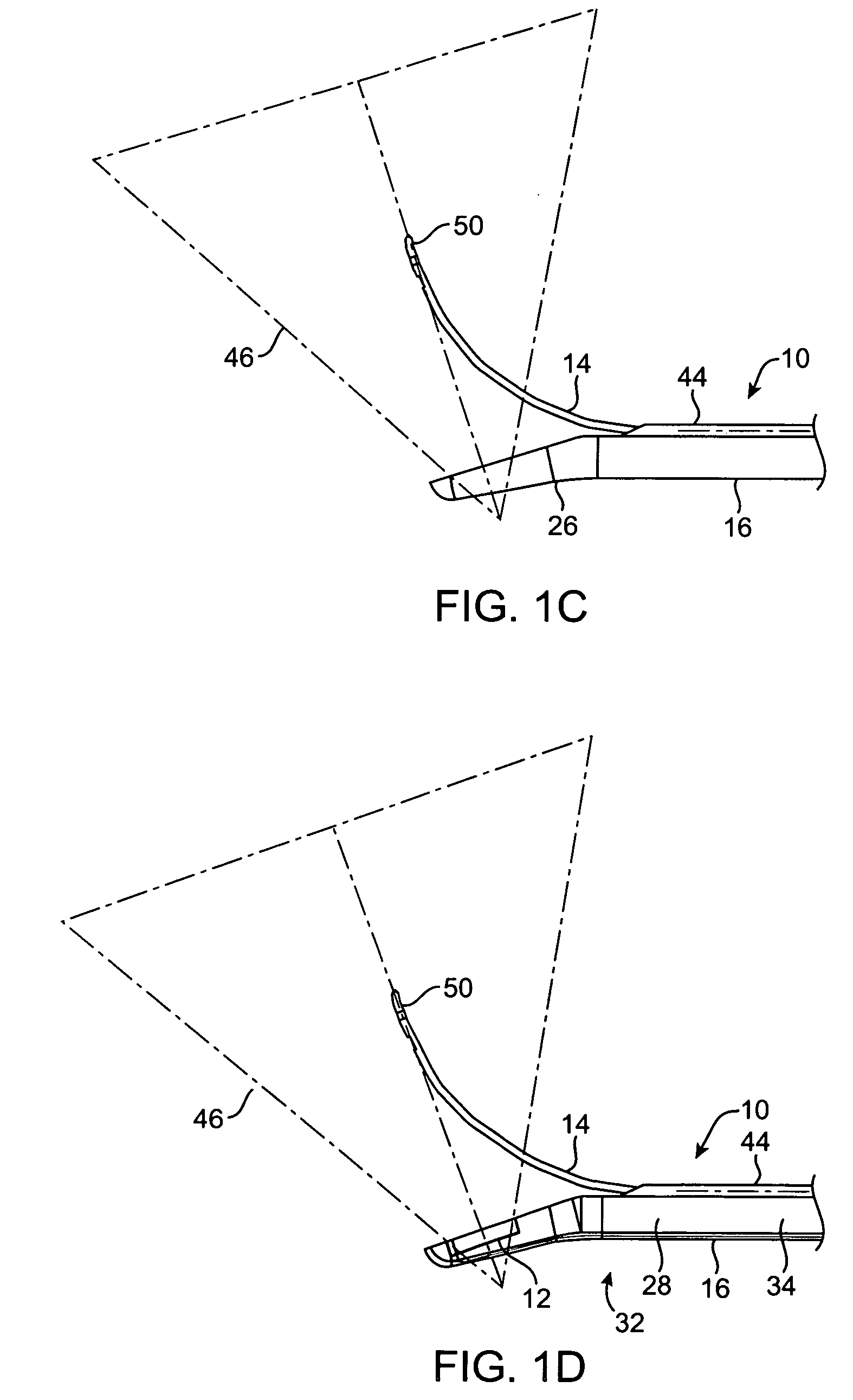
[0047]Referring now to FIGS. 1A through 1D, an exemplary deflectable tip delivery system 10 having an ultrasound array 12 (inclined as shown) for improved imaging and curved needle 14 for ablation treatment of a target site such as fibroid tissues 74 (FIG. 3) within a female's reproductive system, such as uterus 76, is illustrated. The system 10 generally includes a rigid or other delivery shaft 16, an ultrasound imaging insert 28, and an echogenic curved needle 14 with an artifact / feature 100 at a distal end 51 thereof. As shown, the artifact is a retroreflector 105 of a corner cube type 110. The delivery shaft 16 comprises a distal end 18, a proximal end 20, and an axial passage 22 for housing the ultrasound imaging insert 28 therein. A handle 24 may be attachable to the proximal end 20 of the shaft 16. The distal end 18 of the shaft 16 may have a bent or deflectable distal tip 26, as best seen in FIGS. 1B and 1C. The ultrasound imaging insert 28 includes a flexible shaft 34 (see ...


PUM


Abstract

Systems and devices according to the present invention providing a needle deployment and visualization device, which includes: a shaft; an ultrasound imaging transducer extendable along at least a portion of the shaft for providing an image within a field of view; and a needle coupled and deployable from the shaft within the field of view. The needle has an artifact configured to preferentially reflect at least a portion of the ultrasound energy emanating from the ultrasound transducer back to the transducer in order to enhance imaging of the needle.

Description

CROSS-REFERENCES TO RELATED APPLICATIONS[0001]The present application claims the benefit of provisional U.S. Application No. 60 / 938,140 (Attorney Docket No. 025676-001700US), filed May 15, 2007, the full disclosure of which is incorporated herein by reference.[0002]The present application is also related to but does not claim the benefit of U.S. application Ser. No. 11 / 620,594 (Attorney Docket No. 025676-000310US), filed Jan. 1, 2007, entitled “Interventional Deployment and Imaging System Grossman;” U.S. application Ser. No. 11 / 347,018 (Attorney Docket No. 025676-000210US), filed Feb. 2, 2006, entitled “Method and Device for Uterine Fibroid Ablation Grossman;” U.S. patent application Ser. No. 11 / 409,496 (Attorney Docket No. 025676-000700US) filed Apr. 20, 2006, entitled “Rigid Delivery Systems Having Inclined Ultrasound and Curved Needle;” and U.S. patent application Ser. No. 11 / 564,164 (Attorney Docket No. 025676-000710US) filed Nov. 28, 2006, entitled “Devices and Methods for Trea...

Claims


Application Information

Patent Timeline
Patent Type & Authority Applications(United States)
IPC IPC(8): A61B8/00A61B18/18A61M5/32
CPCA61B8/0841A61B8/445A61B8/4488A61B10/0233A61B17/3478A61B18/02A61B18/08A61B18/1477A61B18/18A61B2017/3413A61B2017/4216A61B2018/1425A61B2019/528A61B2019/5425A61B18/1815A61B8/12A61B2090/3784A61B2090/3925
Inventor MUNROW, MICHAEL A.GERBI, CRAIGDECKMAN, ROBERT K.
Owner GYNESONICS
Why Eureka
Try Eureka