
System and method for isotope selective chemical reacations

a chemical reacation and isotope technology, applied in the field of chemical reactions, can solve the problems of difficult to recover unstable products, difficult to make use of unstable intermediate complexes or recover unstable products, and many of these reactions cannot be used in conventional separation processes

Inactive Publication Date: 2009-05-28
MATTHEWS MEHLIN DEAN
View PDF11 Cites 9 Cited by
  • Summary
  • Abstract
  • Description
  • Claims
  • Application Information

AI Technical Summary

Benefits of technology

[0015]In an alternative embodiment the system is coupled to the input of a centrifuge or other mass separation device. The application of electromagnetic radiation and/or magnetic fields to a gas flowing through the reactor provides for a trans...

Problems solved by technology

There are many chemical reactant combinations that may used to provide isotope selective chemical reactions; however, many of these reactions cannot be used in conventional separation processes due to long process timescales.
Transport distances on the order of meters and process durations on the order of minutes make it difficult to make use of unstable intermediate complexes or recover unstable products.
For example, many photolytic and photoexcitation processes can provide considerable initial differentiation between isotopologues in a gas or liquid, but the differentiation may be quickly lost through environmental interaction (e.g., exchange with neighboring species) or photoemission (e.g., fluorescence).
The combination of a tube and waveguide has the disadvantage of low efficiency, particularly if the dimensions of a working cell are below the cutoff frequency of the waveguide.
The prior art of spin conversion does not provide efficient means for producing RF magnetic fields in highly localized regions.

Method used


Image

  • System and method for isotope selective chemical reacations
  • System and method for isotope selective chemical reacations
  • System and method for isotope selective chemical reacations

Examples


Embodiment Construction

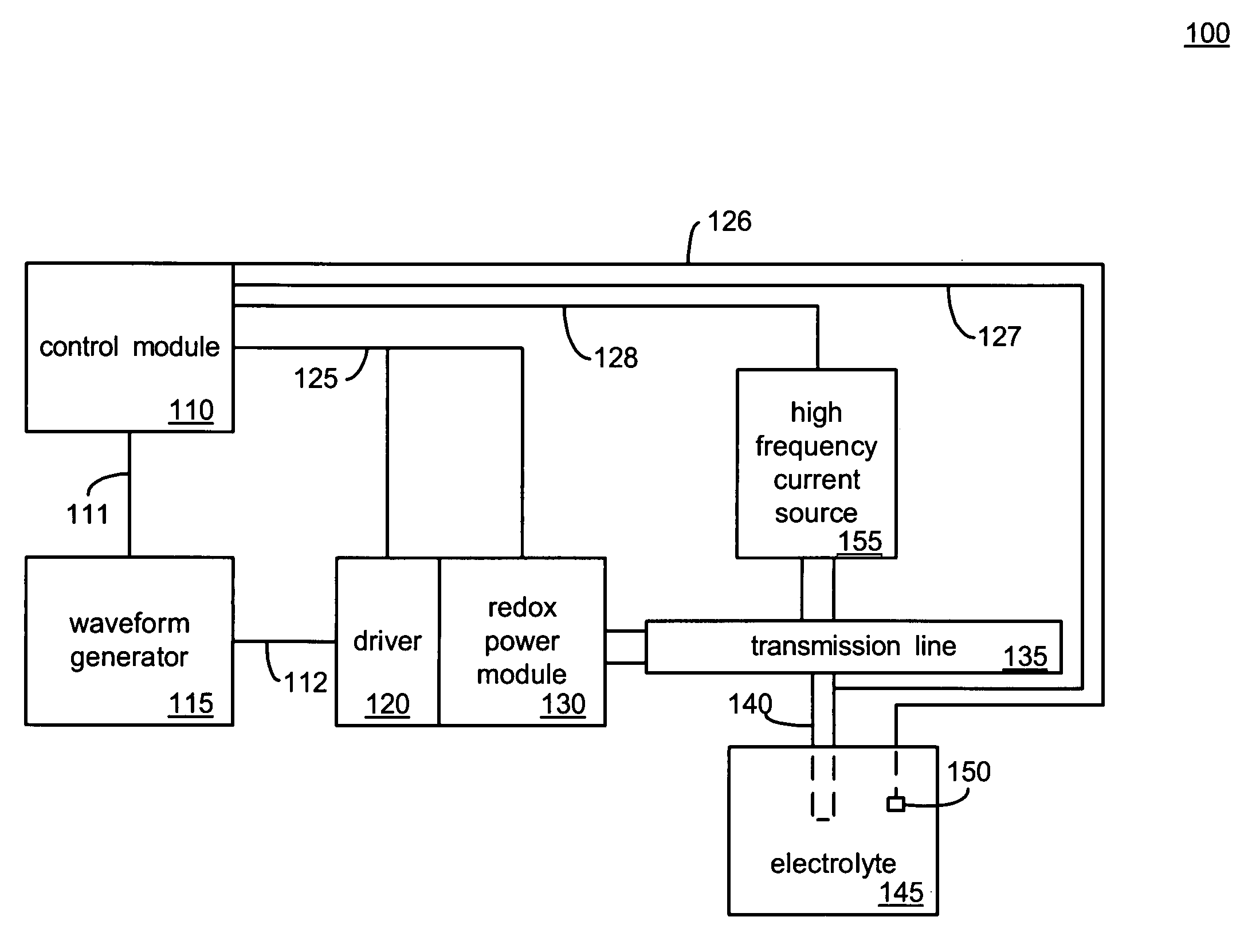
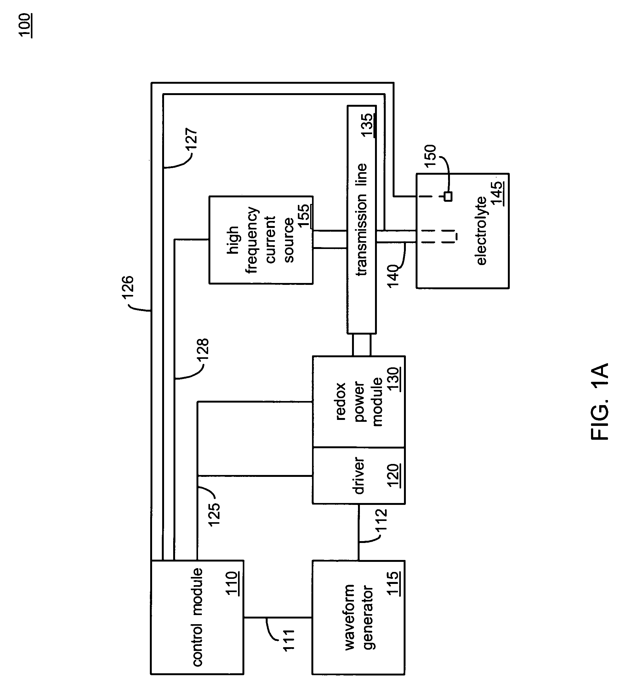
[0078]FIG. 1A shows a block diagram 100 of an embodiment of an electrolytic cell interphase control system. A bus 111 couples a control module 110 to a waveform generator 115. The control module 110 transmits signals to the waveform generator 115 that set the parameters of an output waveform (e.g., duty cycle, amplitude, and period). The bus 111 may also provide feedback to the control module 110 with respect to the output of the waveform generator 115. The output waveform of the waveform generator 115 may include a unipolar signal that has a positive excursion referenced to ground and / or a bipolar signal with positive and negative excursions.

[0079]The waveform generator 115 is coupled to a driver 120 by a signal bus 112. The bus 112 may couple two nodes and carry a single waveform as the output of the waveform generator 115, or it may carry a number of distinct signals between more than two nodes. In a preferred embodiment the driver 120 is driven by an input signal in the range of...


PUM

PropertyMeasurementUnit
Timeaaaaaaaaaa
Frequencyaaaaaaaaaa
Frequencyaaaaaaaaaa

Abstract

A system providing excitation and selective transport and / or reaction of isotopologues. Two or more isotope effects are combined within a reaction cell to produce transient differentiation of isotopologues through excitation or chemical reaction followed by rapid separation or conversion. A current conductor adjacent to a fluid carries an excitation current produced by a switching source. The excitation current produces an alternating magnetic field adjacent to the conductor that interacts with a population of isotopologues within the adjacent fluid layer to produce a population of reaction intermediates or products that have an isotopic composition different from the initial isotopologues. An electrolytic power supply may also be connected to the conductor to provide a voltage that may be used to selectively attract and electrolyze a portion of the reaction intermediates or products within the adjacent fluid layer.

Description

CROSS-REFERENCE TO RELATED APPLICATIONS[0001]This application claims priority of U.S. Provisional Application No. 60 / 990,913, filed Nov. 28, 2007.BACKGROUND OF THE INVENTION[0002]1. Field of the Invention[0003]This invention relates to chemical reactions. In particular, the invention relates to the use of isotope effects to provide selectivity in chemical reactions.[0004]2. Description of Related Art[0005]The transport and reaction of chemical species may be influenced by isotope effects. For example, the classical mass isotope effect (CIE) provides the basis for uranium enrichment by diffusion and by centrifuge. Similarly, isotope effects may be found in electrochemical processes (e.g., the tritium effect), and in photochemical processes (e.g., photoexcitation / photodissociation). The magnetic isotope effect (MIE) may be used to alter the reaction pathways available to chemical reactants, as demonstrated in the photolysis of dibenzyl ketone.[0006]Although there are a variety of isot...

Claims


Application Information

Patent Timeline
IPC IPC(8): C25C3/00
CPCB01D59/38
Inventor MATTHEWS, MEHLIN DEAN
Owner MATTHEWS MEHLIN DEAN
Learn More