Light emitting device with phosphor wavelength conversion and methods of producing the same

a technology of light-emitting devices and phosphor wavelengths, which is applied in the direction of solid-state devices, optical articles, other domestic articles, etc., can solve the problems of color/cct variation that can become a significant problem, color/cct uniformity degradation, etc., and achieve the effect of improving the uniformity of color light outpu

Active Publication Date: 2009-05-28
INTEMATIX
View PDF15 Cites 83 Cited by
  • Summary
  • Abstract
  • Description
  • Claims
  • Application Information

AI Technical Summary

Benefits of technology

[0012]Embodiments of the present invention are directed to light emitting devices with phosphor wavelength conversion and in particular, although not exclusively, to a method of coating the phosphor on to an LED chip / die. In the method of the invention a mixture of a phosphor material and light transmissive material, preferably an optically clear silicone, epoxy or other polymer material, is coated on at least the light emitting surface of the chip, such that the effective size of the resulting light source corresponds to the size of the light emitting surface of the LED chip. As a result the device more closely resembles a point light source and has an improved uniformity of color light output. The effective size of the light source can range in size from a few tens of microns up to several millimeters depending on the dimensions of the LED chip.

Problems solved by technology

A problem with existing light emitting devices with phosphor wavelength conversion is that the color / correlated color temperature (CCT) of light emitted by such devices can vary across the light emitting surface of the device.
Furthermore, the inventors have appreciated that in applications in which the LED includes further optical components, in particular a lens, to focus the output light, such color / CCT variation can become a significant problem.
Moreover, the inventors have further appreciated that a cause of this degradation in color / CCT uniformity results from the LED's poor approximation to an ideal point source.
In addition to the problem of non-uniformity in emitted color / CCT due to the variation in path length through the phosphor / polymer encapsulation, the inventors have discovered that the phosphor material(s) can accumulate unevenly during curing of the liquid polymer resulting in a non-uniform distribution of the phosphor material(s) over the LED chip and in particular on the edges of the LED chip, which will also emit light, where there may be little or no phosphor material(s).
To overcome this problem a greater quantity of phosphor material is often used though this will result in a corresponding decrease in emitted light intensity.
The inventors of the present invention consider that a limitation of such a method is that due to the high viscosity of the phosphor paste the manufacturing method will be too slow for viable mass production.

Method used


Image

  • Light emitting device with phosphor wavelength conversion and methods of producing the same
  • Light emitting device with phosphor wavelength conversion and methods of producing the same
  • Light emitting device with phosphor wavelength conversion and methods of producing the same

Examples


Embodiment Construction

1. Description of Preferred Embodiments

[0038]Throughout this specification the same reference numerals are used to denote like parts.

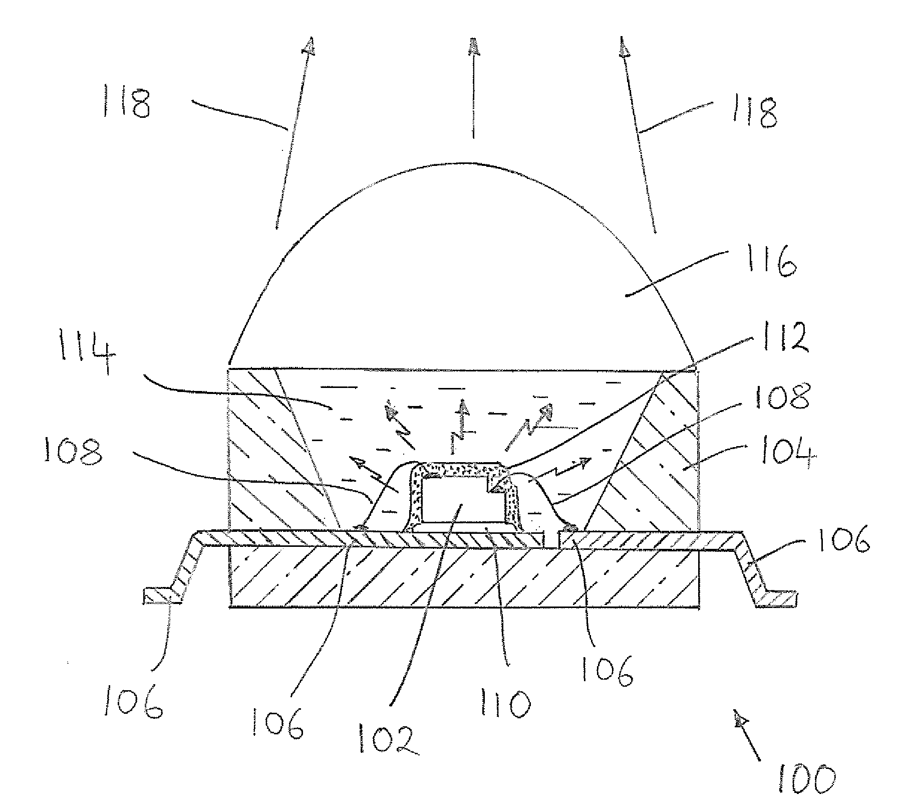
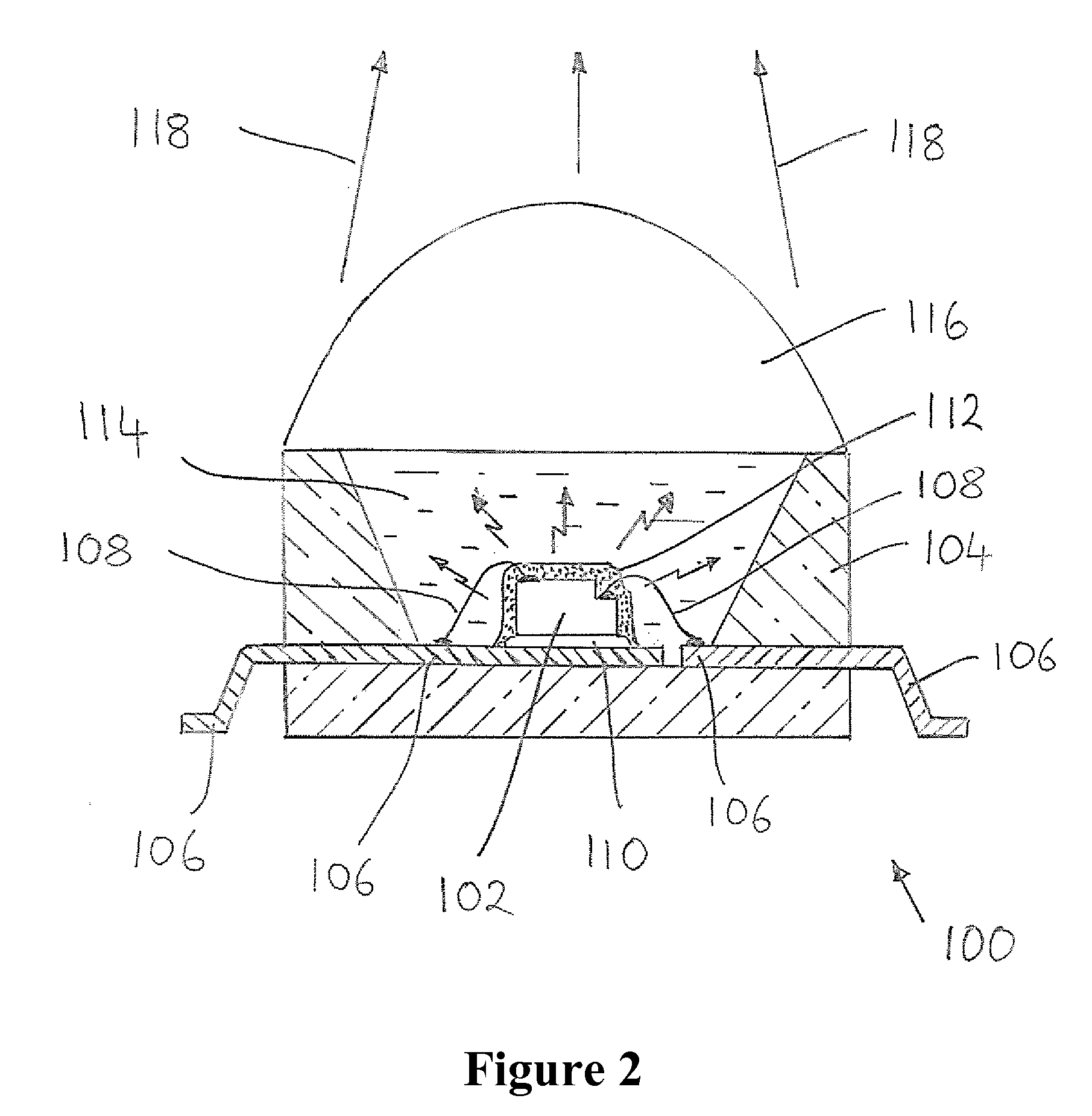
[0039]FIG. 2 is a schematic representation of a light emitting device 100 with phosphor wavelength conversion in accordance with an embodiment of the invention. The device 100 is intended to generate white light and comprises an LED chip 102 which is mounted within a package (housing) 104. As illustrated the package can comprise a low temperature co-fired ceramic (LTCC) package which has a recess for receiving one or more LED chips 102. The walls of the recess are inclined to reflect light in a direction out of the recess. In other arrangements the package 104 can comprise an array of recesses each of which is configured to receive one or more LED chips. Alternatively, the package can comprise a metallic cup, a high temperature polymer package or other package as known in the art. A metallic cup can aid in thermal management of the chip 102.

[0040]The L...


PUM

PropertyMeasurementUnit
thicknessaaaaaaaaaa
thicknessaaaaaaaaaa
temperatureaaaaaaaaaa

Abstract

A method of fabricating a light emitting device comprises: mounting a light emitting diode chip in a package; heating the light emitting diode chip package assembly to a pre-selected temperature; and dispensing a pre-selected volume of a mixture of at least one phosphor and a light transmissive thermosetting material (silicone, epoxy) on a surface of the chip. The pre-selected volume and temperature are selected such that the phosphor/material mixture flows over the entire light emitting surface of the chip before curing. In an alternative method, using a light transmissive UV curable material such as an epoxy, the phosphor/material mixture is irradiated with UV radiation after a pre-selected time to cure the material. The pre-selected volume and pre-selected time are selected such that the phosphor/material mixture flows over at least the light emitting surface of the chip before curing.

Description

CROSS REFERENCE TO RELATED APPLICATIONS[0001]This Application claims the benefit of priority to U.S. Provisional Application Ser. No. 60 / 997,293 filed Oct. 1, 2007, entitled LIGHT EMITTING DEVICE WITH PHOSPHOR WAVELENGTH CONVERSION AND METHODS OF PRODUCING THE SAME, by Li et al., the specification and drawings of which are incorporated herein by reference.BACKGROUND OF THE INVENTION[0002]1. Field of the Invention[0003]The field of the invention is directed to light emitting devices with phosphor wavelength conversion and methods of producing the same. More specifically, the invention concerns light emitting devices based on light emitting diodes (LEDs) and methods of coating one or more phosphor materials on an LED chip.[0004]2. Description of the Related Art[0005]White light generating LEDs (“white LEDs”) are a relatively recent innovation and offer the potential for a whole new generation of energy efficient lighting systems to come into existence. It is predicted that white LEDs ...

Claims


Application Information

Patent Timeline
Patent Type & Authority Applications(United States)
IPC IPC(8): H01L33/00H01L21/56H01L33/44H01L33/50
CPCB29C39/006H01L2224/8592B29C39/10B29L2011/00H01L33/44H01L33/505H01L2933/0041H01L2224/32245H01L2224/48091H01L2224/48247H01L2224/49107H01L2224/73265B29C39/025H01L2924/00014H01L2924/00H01L2924/181H01L2924/00012
Inventor LI, YI-QUNDONG, YI
Owner INTEMATIX
Why Eureka
Try Eureka