
Polarizing Plate Protective Film, Film Producing Method, Polarizing Plate, and Liquid Crystal Display

a technology of protective film and polarizing plate, which is applied in the direction of polarizing elements, instruments, optics, etc., can solve the problems of increased equipment size for drying solvents, increased equipment requirements, and insufficient durability of polarizers over humidity or ultraviolet rays

Inactive Publication Date: 2009-05-28
KONICA MINOLTA OPTO
View PDF7 Cites 27 Cited by
  • Summary
  • Abstract
  • Description
  • Claims
  • Application Information

AI Technical Summary

Benefits of technology

[0040]According to the present invention, it is possible to provide a polarizing plate protective film which employs cellulose ester resin, is produced by a melt casting film forming method and does not exhibit light and dark streaks caused by die lines and spot-like unevenness when an image is displayed on a liquid crystal display, a film producing method, a polarizing plate, and a liquid crystal display.

Problems solved by technology

Namely, a polarizer itself has not sufficient durability over humidity or ultraviolet rays.
In particular, as a monitor and TV are being enlarged more and resolved finely more, such required qualities become more severe.
However, this method has problems that the equipment becomes larger for drying solvents.
However, in comparison with a polymer solution, the viscosity of a molten polymer is usually higher about 10 to 100 times and it may be difficult to level the molten polymer on a support.
Therefore, it may be easy to cause strong streak-like defects called die lines.
If these die lines are too strong, there has been a problem that light and dark streaks caused by die lines are observed when an obtained optical film is built into a liquid crystal display.
Especially, the melt of cellulosic resin has high viscosity and the characteristics which cannot be extended easily.
Therefore, it has been difficult to form a film by the melt casting method.
On the condition where a draw ratio mentioned later is high, there are problems that the thickness unevenness in the film conveying direction (hereafter, the film conveying direction may be referred sometimes to a film longitudinal direction) becomes large and fracture takes place easily in a tenter stretching process.
However, with this method, unevenness of touch pressure could never be removed.
As a result, there is a problem that optical unevenness such as retardation becomes large.
However, in the case where the melt casting film formation of cellulose ester resin was conducted in such ways that the film formation was performed by the use of the elastic touch roller disclosed by the above-mentioned Patent documents 1 and Patent documents 2 and a polarizing plate was produced by the use of the obtained cellulose ester film, the inventor learned that when the produced polarizing plate was installed in a liquid crystal display and the display was used on a black indication mode, there was a problem that light and dark spot-like unevenness was observed overall.
Since a rubber having a high adiathermic is used for this elastic touch roller, even if the touch roller is cooled with a coolant from the inside of the touch roller, the touch roller surface is not fully cooled.
Since minute gaps occur inevitably between a thin metal sleeve and a rubber, the temperature unevenness on the surface of the touch roller is not avoided.
However, the inventor found that as the film forming speed was increased more, concavo-convex-like unevenness and spot-like unevenness occurred on the film surface right after the casting.
Although there is no description about the film forming speed in the above-mentioned patent documents, even when the film forming speed is for example 15m / minutes, the actual situation is that spot-like unevenness is remarkable, productivity is poor and the obtained film cannot be used for actual usage.
However, with this method, the die line is strong.
Therefore, when an image is displayed on a liquid crystal display, there is a problem that light and dark streaks caused by the die lines are observed.
As explained above, the present situation is that a polarizing plate protective film produced by the melt casting film forming method with cellulose ester resin does not reached a practical use level.

Method used


Image

  • Polarizing Plate Protective Film, Film Producing Method, Polarizing Plate, and Liquid Crystal Display
  • Polarizing Plate Protective Film, Film Producing Method, Polarizing Plate, and Liquid Crystal Display
  • Polarizing Plate Protective Film, Film Producing Method, Polarizing Plate, and Liquid Crystal Display

Examples


example of synthesis 1

Synthesis of Example Compound A-1

[0542]After heating 24.6 g (0.116 mol) of 3,4,5-trimethoxybenzoic acid, 100 ml of toluene and 1 ml of N—N-dimethylformamide to 60° C., 15.2 g (0.127 mol) of thionyl chloride was slowly added dropwise, and this mixture was heated at 60° C. for two hours. Then 15.1 g (0.127 mol) of 4-cyanophenol dissolved previously into 50 ml of acetonitryl was slowly added dropwise into this solution. After that, the solution was heated and stirred at 60° C. for 3 hours, and the reaction solution was cooled down to the room temperature. Then ethyl acetate and water were used to perform liquid separation, and sodium sulfate was used to remove water from the organic phase having been obtained. The solvent was distilled off under reduced pressure, and 100 ml of acetonitryl was added to the solid having been obtained, thereby recrystallizing the mixture. The acetonitryl solution was cooled down to the room temperature, and the crystal having been precipitated was recover...

example of synthesis 2

Synthesis of Example Compound A-2

[0546]After heating 106.1 g (0.5 mol) of 2,4,5-trimethoxybenzoic acid, 340 ml of toluene and 1 ml of dimethylformamide to 60° C., 65.4 g (0.55 mol) of thionyl chloride was slowly added dropwise, and this mixture was heated for 2 hours at 65° C. through 70° C. Then 71.5 g (0.6 mol) of 4-cyanophenol previously dissolved into 150 ml of acetonitryl was slowly added dropwise into this solution. After that, the solution was heated and stirred at 80° C. through 85° C. for 2 hours, and the reaction solution was cooled down to the room temperature. Then ethyl acetate (1 L) and water were used to perform liquid separation, and sodium sulfate was used to remove water from the organic phase having been obtained. Approximately 500 ml of solvent was distilled off under reduced pressure, and 1 L of methanol was added to the solid having been obtained, thereby recrystallizing the mixture. The crystal having been precipitated was recovered by filtration, whereby 125....

example of synthesis 3

Synthesis of Example Compound A-3

[0550]After heating 10.1 g (47.5 mM) of 2,3,4-trimethoxybenzoic acid, 40 ml of toluene and 0.5 ml of dimethylformamide to 80° C., 6.22 g (52.3 mM) of thionyl chloride was slowly added dropwise, and this mixture was heated and stirred for 2 hours at 80° C. Then 6.2 g (52.3 mM) of 4-cyanophenol previously dissolved into 20 ml of acetonitryl was slowly added dropwise into this solution. After that, the solution was heated and stirred at 80° C. through 85° C. for 2 hours, and the reaction solution was cooled down to the room temperature. Then ethyl acetate and water were used to perform liquid separation, and sodium sulfate was used to remove water from the organic phase having been obtained. The solvent was distilled off under reduced pressure, and 50 ml of methanol was added, thereby recrystallizing the mixture. The crystal having been precipitated was recovered by filtration, whereby 11.9 g (yield 80%) of the target compound was obtained as a white cr...


PUM

PropertyMeasurementUnit
Linear densityaaaaaaaaaa

Abstract

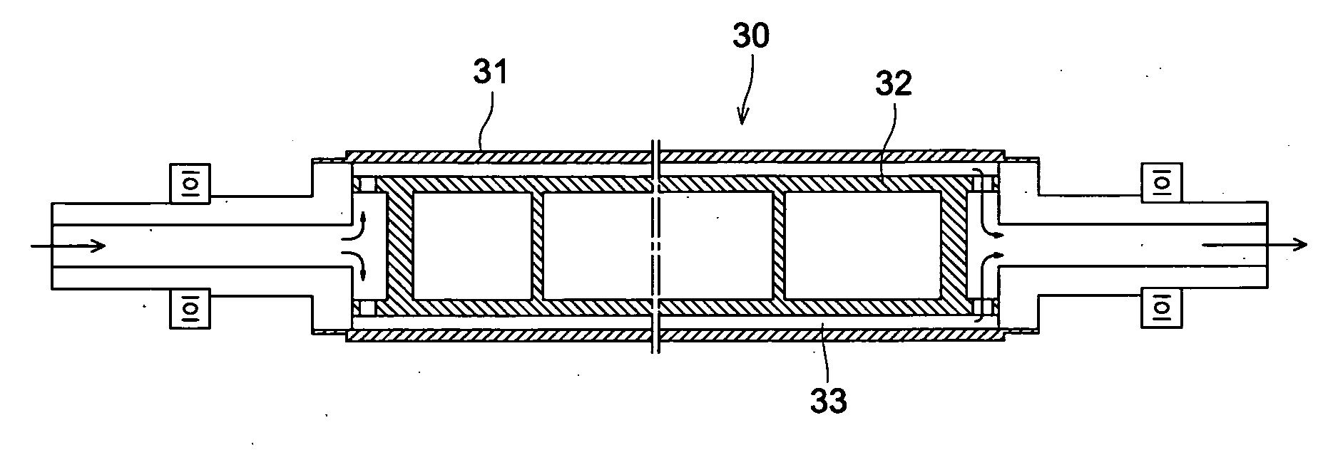
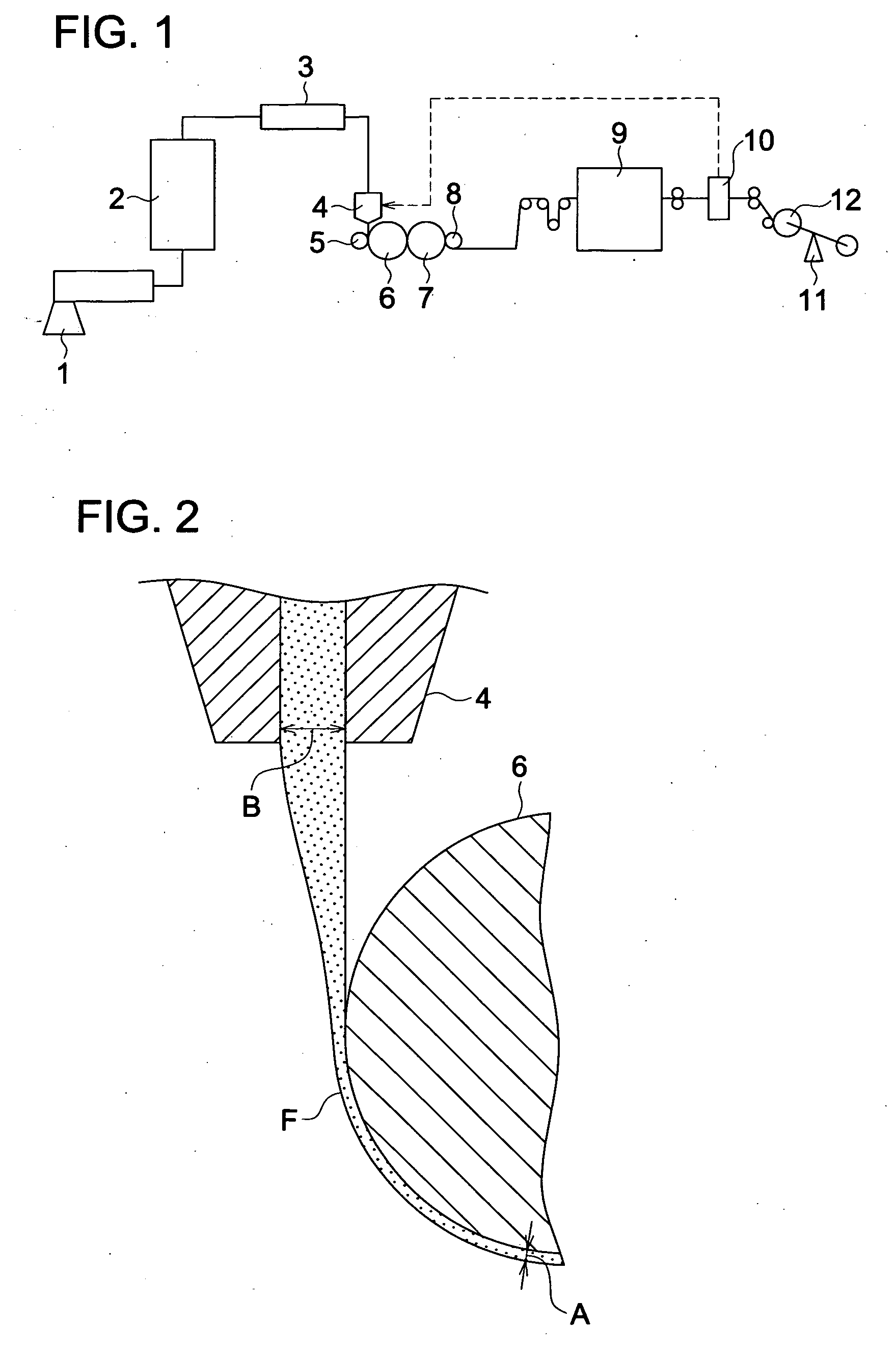
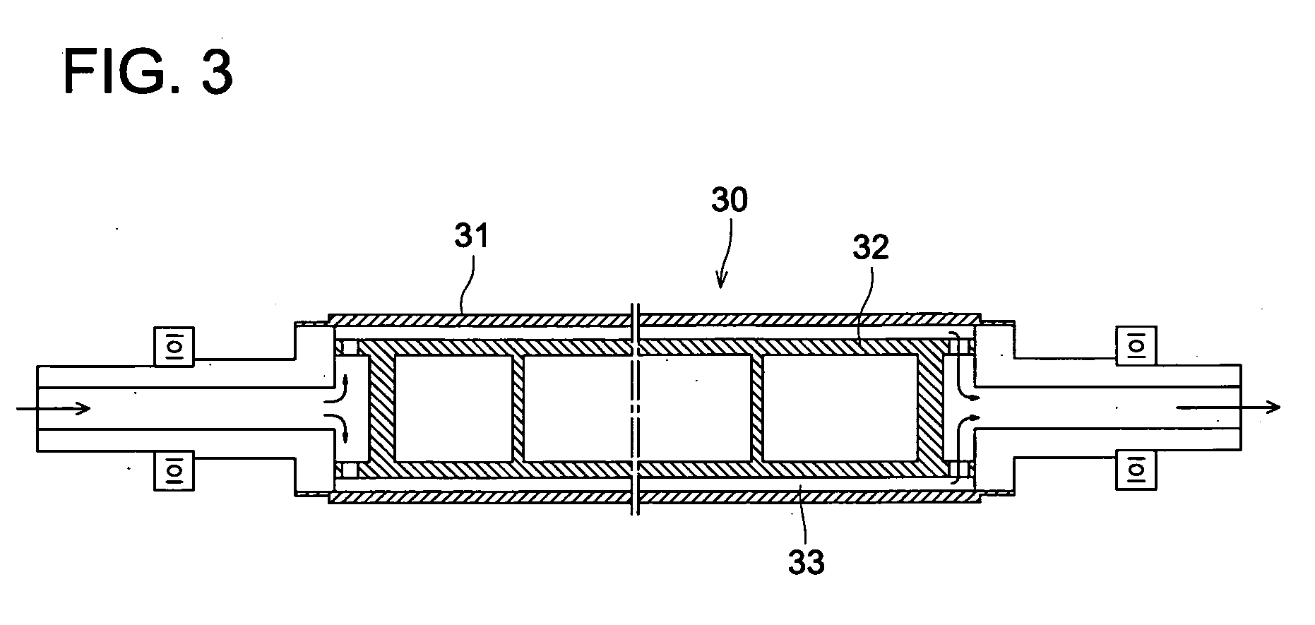
Disclosed is a method for production of a film, which comprises the steps of: extruding a molted material containing a cellulose resin on a cooling roll from a die in a film-like form at a draw ratio ranging from 10 to 30 inclusive; pressing the extruded molted film on the cooling roll with a touch roll; and transferring the molted film while solidifying the film on the cooling roll, wherein the touch roll has a metal-made outer cylinder, an inner cylinder, and a space for accommodating a cooling medium between the metal-made outer cylinder and the inner cylinder and also has a touch roll linear pressure ranging from 1 to 15 kg / cm inclusive during pressing with the touch roll.

Description

TECHNICAL FIELD[0001]The present invention relates to a polarizing plate protective film, film producing method, polarizing plate, and liquid crystal display, in particular, to the polarizing plate protective film which employs cellulose ester resin, is produced by a melt casting film forming method and does not exhibit light and dark streaks caused by die lines and spot-like unevenness when an image is displayed on it with a liquid crystal display, the film producing method, the polarizing plate, and the liquid crystal display.BACKGROUND ART[0002]In comparison with conventional CRT displays, a liquid crystal display has been widely used as a monitor from viewpoints of space saving and energy saving. Furthermore, it becomes popular to be used for TV. For such a liquid crystal display, various kinds of optical films such as polarizing plate protective film, retardation film, antireflection film, luminance improving film are used.[0003]In a polarizing plate, a cellulose ester film is ...

Claims


Application Information

Patent Timeline
IPC IPC(8): G02F1/1335G02B1/08B29C67/00B29C48/08B29C48/305B29C48/92
CPCB29C47/0021B29C47/0078B29C47/10B29C47/1018B29C47/14B29C47/8845B29C47/92B29C2791/006B29K2105/256G02B1/105G02B5/3033B29C47/1036B29C47/886B29C48/92B29C2948/92209B29C2948/92704B29C48/08B29C48/143B29C48/285B29C48/287B29C48/2883B29C48/305B29C48/91B29C48/914B29C48/9155B29C2948/92152B29C2948/92428B29C2948/92438B29C2948/92523B29C2948/92647B29C2948/92904B29C2948/92923B29C2948/92933G02B1/14G02B5/30B29C48/30
Inventor YAJIMA, TAKATOSHIMURAKAMI, TAKASHI
Owner KONICA MINOLTA OPTO
Learn More