Optical transmission system and optical node

a transmission system and optical node technology, applied in the field of optical transmission systems and optical nodes, can solve problems such as the complexity of the management of passes

Inactive Publication Date: 2009-05-28
HITACHI LTD
View PDF5 Cites 11 Cited by
  • Summary
  • Abstract
  • Description
  • Claims
  • Application Information

AI Technical Summary

Benefits of technology

[0004]The problem noted above can be addressed by an optical transmission system including plural optical nodes capable of dropping or adding optical signals and a monitoring and controlling device that monitors and controls these optical nodes, wherein each of the optical nodes is provided with an optical transceiver and an optical add-drop unit that sends out optical signal from the optical transceiver to a transmission line or guides optical signal from the transmission line to the optical transceiver; the optical add-drop unit selects, regarding add signals, optical signals from the optical transceiver of an own node thereof or optical signals from a second transmission line for optical signals to be sent out to a first transmission line, regarding drop signals, drops signals from the first transmission line to the own node thereof and at the same time sends out the same to the second transmission line or intercepts sending-out of the same to the second transmission line; and an alarm inhibiting device is further provided that, regarding transmit signals from a first optical transceiver of a first optical node, inhibits any unexpected alarm from being issued by the first optical transceiver when selection is made by the optical add-drop unit of a second optical node to drop the signals to the own node thereof and to send the same out to a transmission line in a downlink direction. The problem can also be addressed by an optical node including an optical transceiver and an optical add-drop unit that sends out optical signal from the optical transceiver to a transmission line or guides optical signal from the transmission line to the optical transceiver, wherein the optical add-drop unit, when, regarding drop signals, the unit drops signals from a first transmission line to the own node thereof and sends out the same to a second transmission line, selects, regarding add signals, optical signals from the optical transceiver of the own node thereof as optical signals to be sent out to the first transmission line and intercepts sending-out of receive signals from the second transmission line.

Problems solved by technology

However, this is regarded as involving the following problem.
Moreover, pass management is made more complex by the mixed presence of one-to-one type paths and one-to-N type paths.

Method used


Image

  • Optical transmission system and optical node
  • Optical transmission system and optical node
  • Optical transmission system and optical node

Examples


embodiment 1

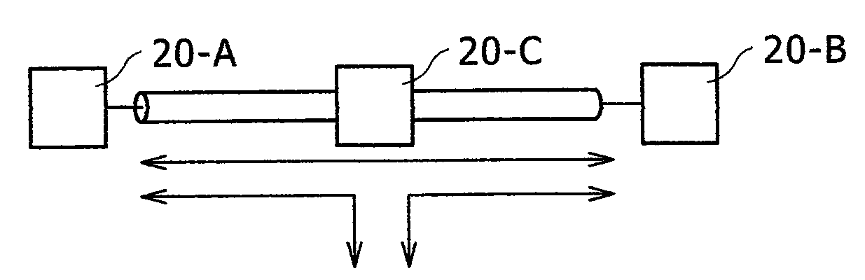
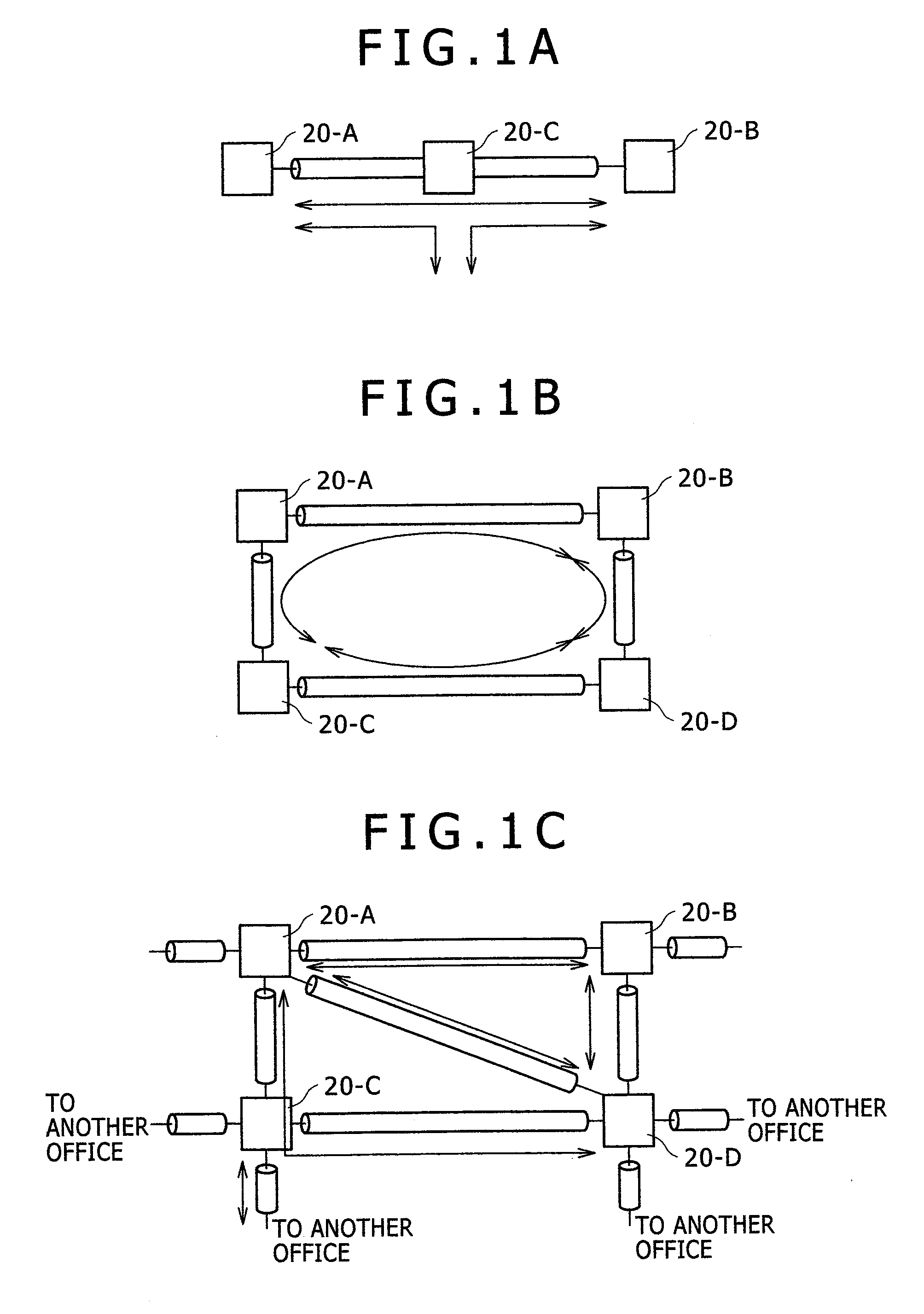
[0016]Network forms will be described with reference to FIGS. 1A to 1C. FIG. 1A shows a configuration having two offices 20-A and 20-B at the terminal points and office 20-C between office 20-A and office 20-B, which are connected to one another by transmission line fibers. It is a linear-shaped network in which at least part of signals added at office 20-A or office 20-B can be dropped at office 20-C and other signals can be added at office 20-C. Solid lines here indicate that paths are set between office 20-A and office 20-B, between office 20-A and office 20-C, and between office 20-C and office 20-B.

[0017]FIG. 1B shows a ring-shaped network. In the ring-shaped network, office 20-A, office 20-B, office 20-C and office 20-D are connected to the respectively adjoining offices 20 by transmission line fibers. As the network constitutes a ring, even if a fiber runs into fault in one position, the network can be protected by transmission in the reverse way. Moreover, the network can be...

embodiment 2

[0025]Control of dropping and addition when a receiving node is to be added to the optical transmission system will be described with reference to FIG. 8 and FIG. 9. In FIG. 8, it is supposed that a one-to-N type optical path having office A as the transmitting node and offices B and C as the receiving nodes is set in the optical transmission system 10. The flow of signals in this state is represented by thick solid lines. The states of the drop function unit 140 and the add function unit 150 in the WDM optical switching unit 40 are stated in the “Before addition” line in FIG. 9. In FIG. 9, the drop function unit is expressed as “D” and the add function unit, as “A”. In the list, “D.C.” means irrelevant and “DITTO”, the same as above. As the add function unit, a 2×1 optical switch or WSS can be used, and this unit is functionally a selector. Referring back to FIG. 8, addition of office D as a receiving node to the one-to-N type optical path of the optical transmission system 10 will...


PUM


Abstract

Where an integrated monitoring and controlling unit is to control an optical add-drop unit so as to cause transmit signals from the optical transceiver of a first optical node to be received by the optical transceivers of plural different optical nodes, this purpose can be achieved by an optical transmission system provided with an alarm inhibiting device that can inhibit the optical transceiver, which is a source of transmission, from issuing any unexpected alarm.

Description

CLAIM OF PRIORITY[0001]The present application claims priority from Japanese patent application serial no. 2007-303317, filed on Nov. 22, 2007, the content of which is hereby incorporated by reference into this application.BACKGROUND OF THE INVENTION[0002]The present invention relates to an optical transmission system and an optical node, and more particularly to an optical transmission system and an optical node capable of receiving a transmitted signal at plural nodes. The rapid increase in data traffic, typically over the Internet, is pushing ahead the expansion of transmission capacities of communication networks. Capacity expansion is achieved by converting transmit signals into optical signals and utilizing time division multiplexing or optical wavelength division multiplexing. A transmission device whose capacity is 10 gigabits per second per channel is now available for practical use. A point-to-point wavelength division multiplexing transmission device, which is capable of ...

Claims


Application Information

Patent Timeline
Patent Type & Authority Applications(United States)
IPC IPC(8): H04B10/00H04B10/07H04B10/077H04B10/27H04B10/278H04B10/29
CPCH04J14/0204H04J14/0213H04J14/0212H04J14/0208
Inventor FUKASHIRO, YASUYUKI
Owner HITACHI LTD
Why Eureka
Try Eureka