
Rotary Burr Comprising Cemented Carbide

a technology of cemented carbide and rotary burrs, which is applied in the field of tools, can solve the problems of creating ragged edges or small protrusions referred to as “burrs” on metallic articles, urgent and as-yet unsatisfactory need to develop improved tools capable of efficiently and cost-effectively machining difficult-to-machine materials, etc., and achieves the effect of improving cutting performance and tool wear resistance, improving efficiency and cost-effectiveness

Inactive Publication Date: 2009-05-28
ATA TOOLS
View PDF43 Cites 47 Cited by
  • Summary
  • Abstract
  • Description
  • Claims
  • Application Information

AI Technical Summary

Benefits of technology

[0010]According to one non-limiting aspect of the present disclosure, an embodiment of an improved rotary burr comprising cemented carbide includes a shank for attaching the rotary burr to a machine tool and a working portion. A surface of the working portion includes a plurality of right-handed helically oriented flutes that define a plurality of cutting teeth adapted for removing material from a workpiece. Each of the plurality of cutting teeth defined by the right-handed flutes includes a front face, a back face, and a tip, and has a positive front face angle (as defined hereinbelow). Each of the plurality of cutting teeth defined by the right-handed flutes also lacks a radial land adjacent the tooth tip at the periphery of the working portion. The inventors unexpectedly discovered that a rotary burr having this novel design provides significantly improved cutting performance and tool wear resistance, and allows for the machining of titanium, titanium alloys, and other difficult-to-machine alloys in a significantly more efficient and cost-effective manner.
[0015]Certain non-limiting embodiments of a rotary burr comprising cemented carbide constructed according to the present disclosure may comprise a single-layer or multiple-layer surface coating on at least a region of the working portion of the rotary burr to enhance tool wear resistance and / or performance characteristics. Examples of possible surface coatings include chemical vapor deposition (CVD) coatings, physical vapor deposition (PVD) coatings, and diamond coatings.

Problems solved by technology

Metals and metallic alloys may be welded, molded, cast, trimmed, slit, drilled, sheared, or machined, and these techniques often create ragged edges or small protrusions referred to as “burrs” on the metallic articles.
Therefore, there exists an urgent and as-yet unsatisfied need to develop improved tools capable of efficiently and cost-effectively machining difficult-to-machine materials.

Method used


Image

  • Rotary Burr Comprising Cemented Carbide
  • Rotary Burr Comprising Cemented Carbide
  • Rotary Burr Comprising Cemented Carbide

Examples


embodiment 10

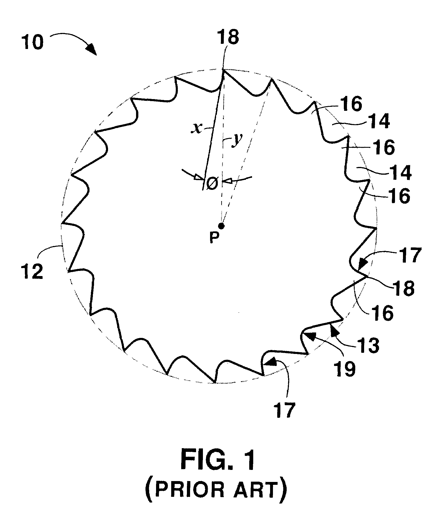
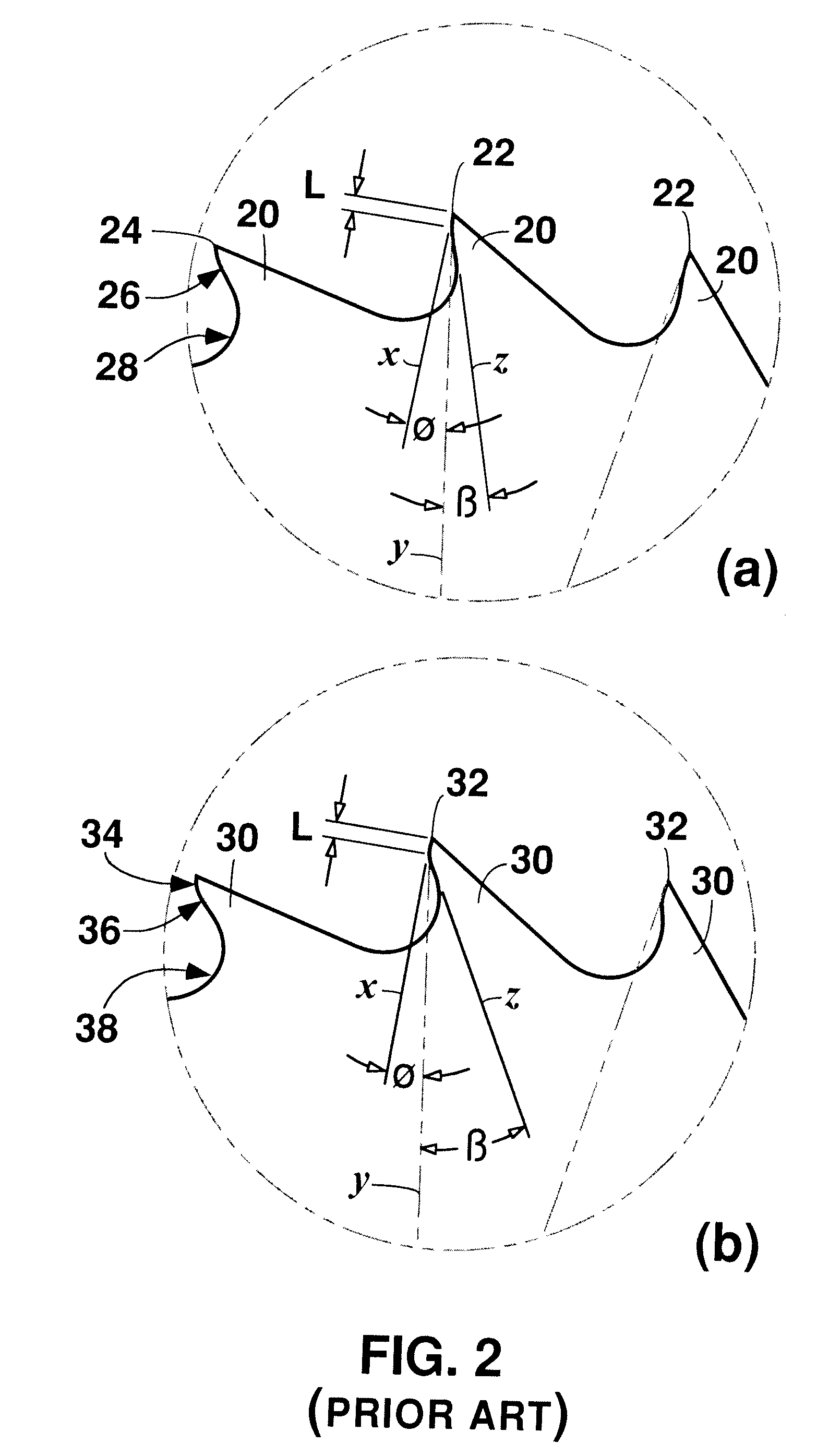
[0041]Aspects of embodiments of rotary burrs constructed according to the present disclosure will be understood by comparing such tools with FIG. 1, which is a schematic cross-sectional view approximately mid-way along the length of the working portion and at a right angle to the rotational axis of an embodiment 10 of a conventional cemented carbide rotary burr. As used herein, the “working portion” of a rotary burr is the region of the tool that has been ground or otherwise machined to include the cutting teeth. The working portion may also be referred to as, for example, the “burr head” of the tool. Dotted line 12 indicates the original periphery of the tool blank which has been ground at one end to form the working portion of the rotary burr 10. The rotational axis of rotary burr 10 is indicated as point P, and the tool further includes flutes 14 defining teeth 16. Each tooth 16 includes a front face 17, a tip 18, and a back face 13, which leads into an arc 19 transitioning to th...

embodiment 40

[0045]FIG. 3 is a schematic cross-sectional view approximately mid-way along the working portion and at a right angle to the rotational axis of another conventional cemented carbide rotary burr embodiment 40 showing the profile of teeth 46, defined by flutes 44, about the circumference of the rotary burr 40. Dotted line 42 is the original periphery of the blank from which the rotary burr 40 was ground. Each tooth 46 depicted about the cross-section of burr 40 includes a tip 41, a radial land 47 between the tooth front face 48 and the tooth back face 49, and each radial land 47 approximates the original periphery 42 of the cylindrical blank from which the tool was ground. Using lines Y drawn from the cylindrical axis P to adjacent tooth tips 41 and lines X drawn from a tooth tip 41 and along the surface of the front face 48, it will be seen that the front face angle Ø of each tooth is a negative angle as the rotational direction from line X to line Y for a particular tooth is counter...


PUM

PropertyMeasurementUnit
Angleaaaaaaaaaa
Compositionaaaaaaaaaa

Abstract

A rotary burr comprising cemented carbide for removing material from a workpiece includes a shank and a working portion and a shank. A surface of the working portion includes a plurality of right-handed helically oriented flutes that define a plurality of cutting teeth on the working portion. Each of the plurality of cutting teeth defined by the right-handed flutes includes a front face, a back face, a tip, and a positive front face angle, and lacks a radial land adjacent the tooth tip and at the periphery of the working portion.

Description

BACKGROUND OF THE TECHNOLOGY[0001]1. Field of Technology[0002]The present disclosure relates to tools used for deburring and / or finishing articles. More particularly, the present disclosure relates to cemented carbide rotary burrs useful for removing material from articles composed of, for example, metals, metallic alloys, or certain non-metallic materials.[0003]2. Description of the Background of the Technology[0004]Rotary burrs formed from cemented carbide are known and are commonly used for abrading and smoothing metal and metallic alloy articles. Rotary burrs are available in various shapes, sizes, and abrasive textures, depending on the tool's intended application. Metals and metallic alloys may be welded, molded, cast, trimmed, slit, drilled, sheared, or machined, and these techniques often create ragged edges or small protrusions referred to as “burrs” on the metallic articles. The process by which the edges are finished and the protrusions are removed commonly is referred to...

Claims


Application Information

Patent Timeline
IPC IPC(8): B23B27/20B23B27/22
CPCB23B2222/28B23C5/10B23C2210/03B23C2210/0442B23C2210/0457Y10T408/81B23C2210/326B23C2222/88Y10T407/1952Y10T408/9097B23C2210/088
Inventor NEWITT, ALANPAYNE, DAVID JOHNFANG, X. DANIELWILLS, DAVID J.
Owner ATA TOOLS
Learn More