Vacuum package and manufacturing process thereof

a vacuum package and manufacturing process technology, applied in the field of vacuum package, can solve the problems of high inability to completely seal through hole b>943/b>, and increase the risk of short circuit caused by whisker as time passes, so as to achieve enhanced air tightness (belmetic sealing property) of vacuum package, the effect of high evacuation

Inactive Publication Date: 2009-06-04
NEC CORP
View PDF4 Cites 19 Cited by
  • Summary
  • Abstract
  • Description
  • Claims
  • Application Information

AI Technical Summary

Benefits of technology

[0037]According to the present invention, a through hole having large conductance can be formed without need of a large opening area, because a neck portion having a minimum opening area is formed in the middle of the through hole. Accordingly, the vacuum package can be downsized, and high evacuation and short-time evacuation of (interior of) the vacuum package can be achieved.
[0038]According to the present invention, occurrence of a crack in an edge portion of the through hole can be suppressed even if a fragile material is used because the edge portion of the through hole has an obtuse angle. Accordingly, the airtightness (belmetic sealing property) of the vacuum package can be enhanced.
[0039]According to the present invention, the sealing material or whisker is prevented from entering into a chamber by forming a pad for a sealing material on only a first taper surface in the inner wall of the through hole. Accordingly, a functional fault or electrical short circuit can be prevented. The through hole can be also sealed at a part having the minimum opening area. Therefore, occurrence of a sealing defect can be prevented.

Problems solved by technology

In this mode, however, the sealing material 944 flows so as to avoid the opening of the through hole 943 as shown in FIG. 27B or falls down through the through hole 943, so that there arises a problem that the through hole 943 can not be sealed completely.
If the diameter of the opening of the through hole 943 is wide, a defect of the sealing tends to arise especially.
If lead-free solder is used as the sealing material 954, especially, because a needle whisker of Sn tends to grow, a risk of the short circuit caused by the whisker which grows as time passes becomes higher even if the solder is not in direct contact with the wire in an initial stage.
In this case, however, the package can not be made thinner.

Method used


Image

  • Vacuum package and manufacturing process thereof
  • Vacuum package and manufacturing process thereof
  • Vacuum package and manufacturing process thereof

Examples


example 1

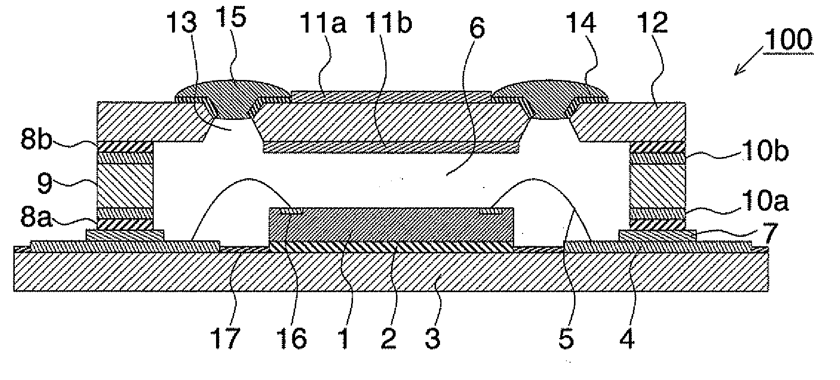
[0119]An example of the vacuum package of the present invention will be explained. A manufactured vacuum package was the vacuum package for the infrared sensor as shown in FIG. 1 and had an infrared receiving component as the functional component. The through hole was formed in the infrared transmission window like the first exemplary embodiment.

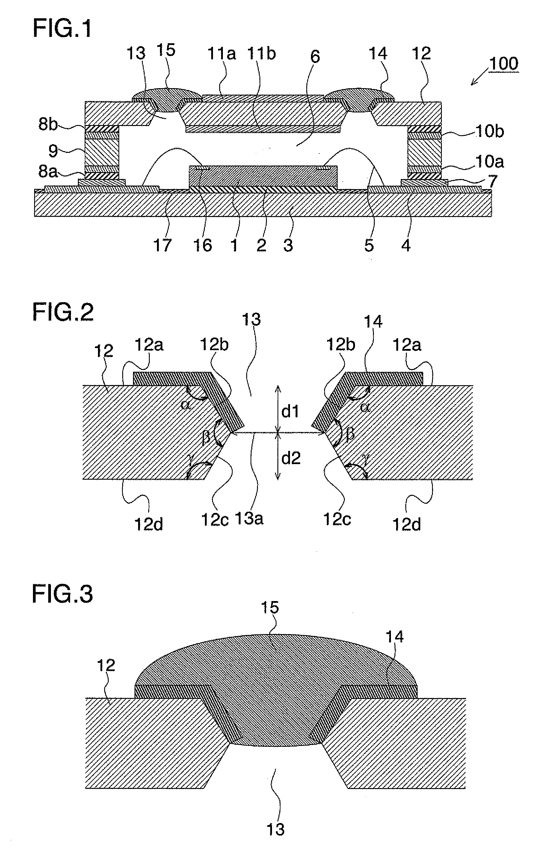
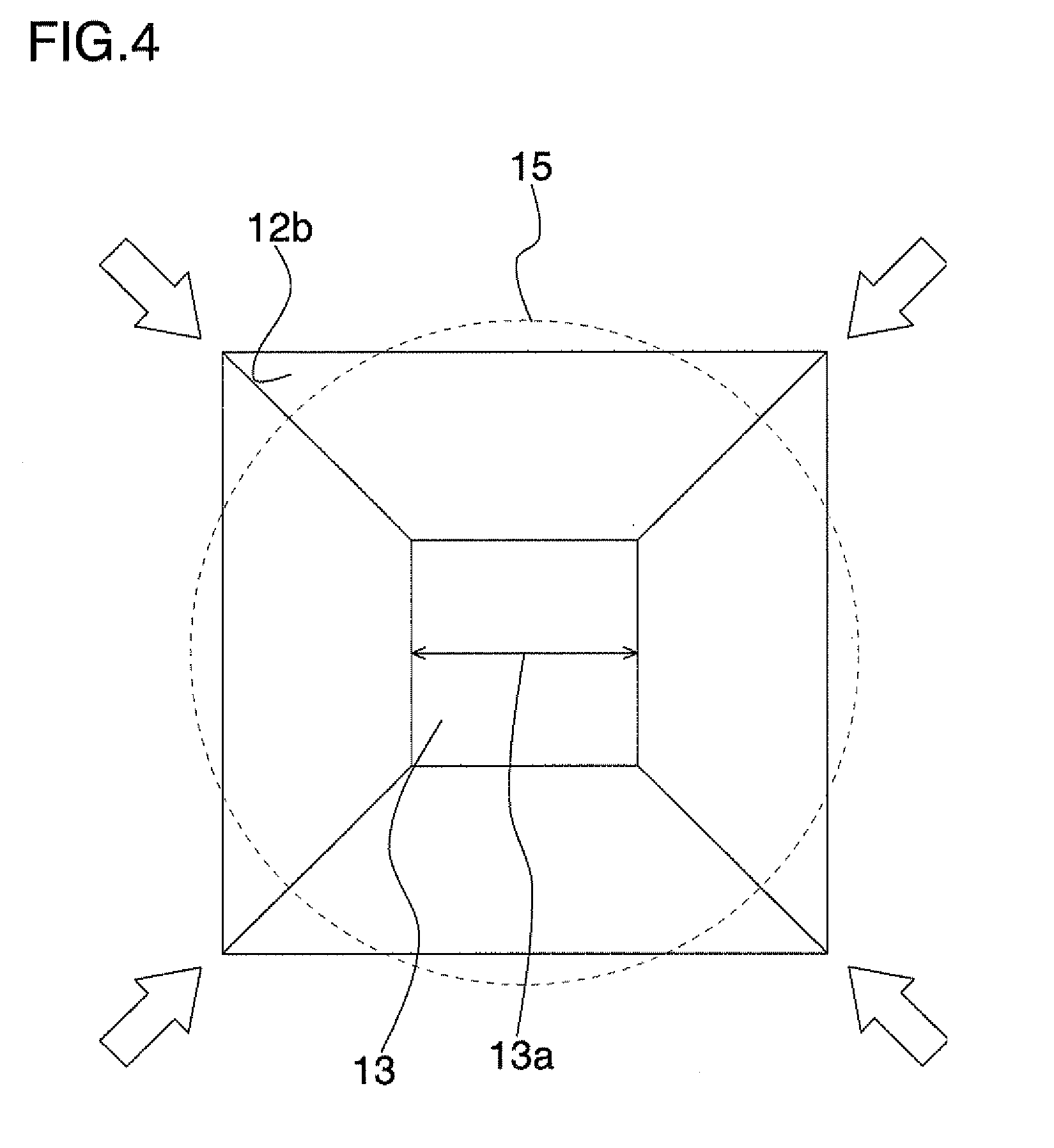
[0120]A silicon substrate for the infrared transmission window having the antireflection coatings, the sides of, e.g. 16.2 mm×16.2 mm and a thickness of, e.g. 0.8 mm was prepared, and the anisotropic etching was treated with e.g. KOH from both surfaces of the silicon substrate to form the through holes. As shown in FIG. 2 according to the first exemplary embodiment, the formed through holes had the first and second taper surfaces with the same depth to form the neck part at the middle of the through hole and the symmetry to the center line of the through hole. The opening shape of the through hole on the substrate surface was a square 0.726 ...


PUM


Abstract

A vacuum package has a chamber in which pressure is reduced to less than the atmospheric pressure, a functional component sealed in the chamber, and a material forming at least a part of the chamber. The material has at least one through hole to evacuate the chamber. In a cross section perpendicular to the material taken along the through hole, an edge portion of the material forming the through hole has an obtuse angle. The through hole is sealed with a sealing material.

Description

REFERENCE TO RELATED APPLICATION[0001]This application is based upon and claims the benefit of the priority of Japanese patent application No. 2007-310694, filed on Nov. 30, 2007, the disclosure of which is incorporated herein in its entirety by reference thereto.TECHNICAL FIELD[0002]This invention relates to a package vacuum-sealing a functional component (an infrared detecting component, a piezoelectric component, and an oscillating component, for example) termed “vacuum package” herein, and manufacturing process thereof.BACKGROUND[0003]In a functional device such as an infrared sensor, a pressure sensor, and an acceleration sensor, it is necessary to vacuum-seal each functional component in order to enhance its performance.[0004]Giving an example of the infrared sensor, there are a quantum type and a heat type as an infrared detecting component generally, the heat type being a type of detecting relative quantity of heat. Although a following performance of the heat type is inferi...

Claims


Application Information

Patent Timeline
Patent Type & Authority Applications(United States)
IPC IPC(8): G01J5/04B65B31/00G01J1/02H01L23/02
CPCH01L23/047H01L23/057H01L2224/45124H01L24/48H01L2924/16195H01L27/14618H01L31/0203H01L2224/48091H01L2224/48227H01L2924/01046H01L2924/01078H01L2924/01079H01L2924/09701H01L2924/16151H01L2924/00014H01L2924/00B81C1/00285B81C2203/0145H01L24/45H01L2224/45015H01L2924/12042H01L2924/20753H01L2224/05599
Inventor SOGAWA, YOSHIMICHIYAMAZAKI, TAKAOSANO, MASAHIKOKURASHINA, SEIJIAKIMOTO, YUJI
Owner NEC CORP
Why Eureka
Try Eureka