Power Supply Unit

a power supply unit and power supply technology, applied in the direction of gas pressure propulsion mounting, propulsion parts, electric devices, etc., can solve the problems of increasing the size of the entire cooling device, complicated control, and inability to mount a configuration in a vehicle, so as to achieve simple configuration, simple configuration, and small size

Active Publication Date: 2009-06-04
TOYOTA JIDOSHA KK
View PDF10 Cites 45 Cited by
  • Summary
  • Abstract
  • Description
  • Claims
  • Application Information

AI Technical Summary

Benefits of technology

[0016]According to the power supply unit described above, by allowing the cooling medium to flow, through the second power supply with a lower temperature, into the first power supply with a higher temperature, the first power supply and the second power supply can be cooled using a common cooling device. As a result, the entire power supply unit can be configured to be compact.
[0040]Further, temperatures of a plurality of power supplies constituting the power supply unit can be adjusted with a simple configuration.

Problems solved by technology

However, such a configuration requires to be provided with a plurality of cooling fans, resulting in an increase in the size of the entire cooling device, and thus the configuration may not be suitable to be mounted in a vehicle having severe mounting space constraints.
Further, since the amount of cooling wind is controlled for each of the plurality of the cooling fans, there arises a problem that the control is complicated.

Method used


Image

  • Power Supply Unit
  • Power Supply Unit
  • Power Supply Unit

Examples


first embodiment

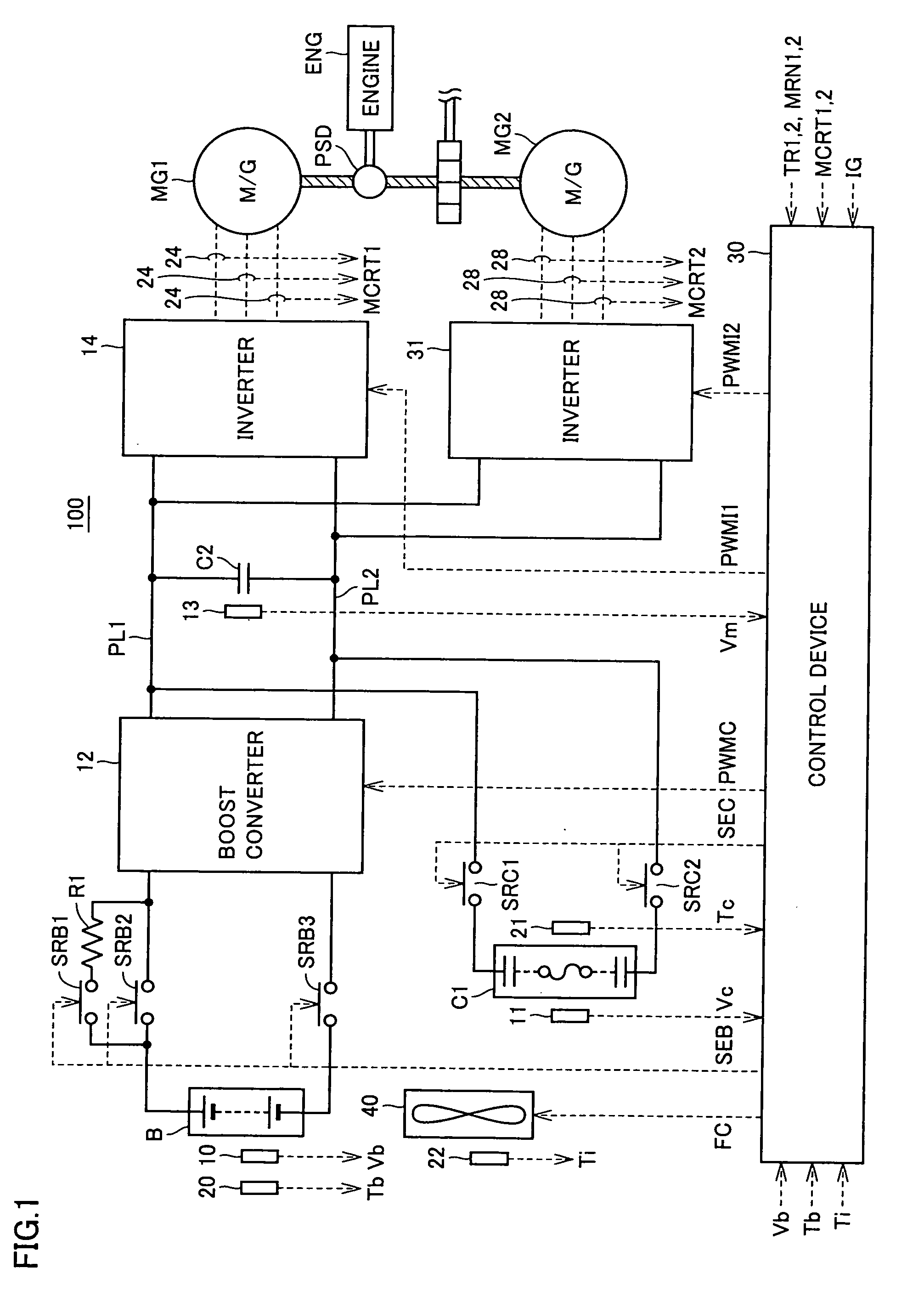
[0051]FIG. 1 is a schematic block diagram of a motor drive device to which a power supply unit in accordance with a first embodiment of the present invention is applied.

[0052]Referring to FIG. 1, a motor drive device 100 includes a battery B, a boost converter 12, a power storage device C1, a capacitor C2, inverters 14 and 31, voltage sensors 10, 11, and 13, current sensors 24 and 28, temperature sensors 20-22, a cooling device 40, system relays SRB1-SRB3, SRC1, and SRC2, a resistor R1, and a control device 30.

[0053]An engine ENG generates drive force using combustion energy of a fuel such as gasoline as a source. The drive force generated by engine ENG is split by a motive power split mechanism PSD into two paths, as indicated by thick diagonal lines in FIG. 1. One is a path transmitting the split drive force to a drive shaft driving wheels via a decelerator not shown, and the other is a path transmitting the split drive force to a motor generator MG1.

[0054]While motor generators M...

second embodiment

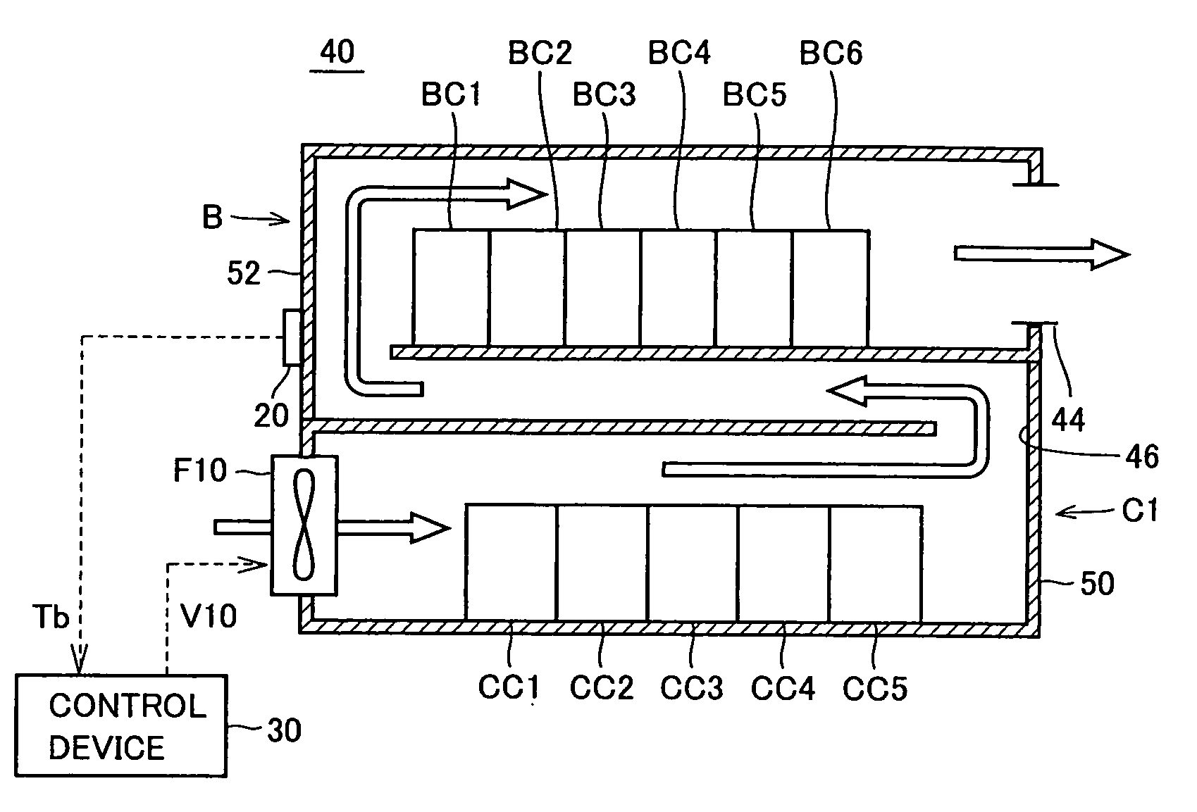
[0119]As described in the aforementioned first embodiment, both power storage device C1 and battery B can be cooled efficiently using common cooling wind by stacking battery B with a higher temperature above power storage device C1 with a lower temperature and forming the cooling wind flow path to allow the cooling wind to flow from power storage device C1 with a lower temperature to battery B with a higher temperature.

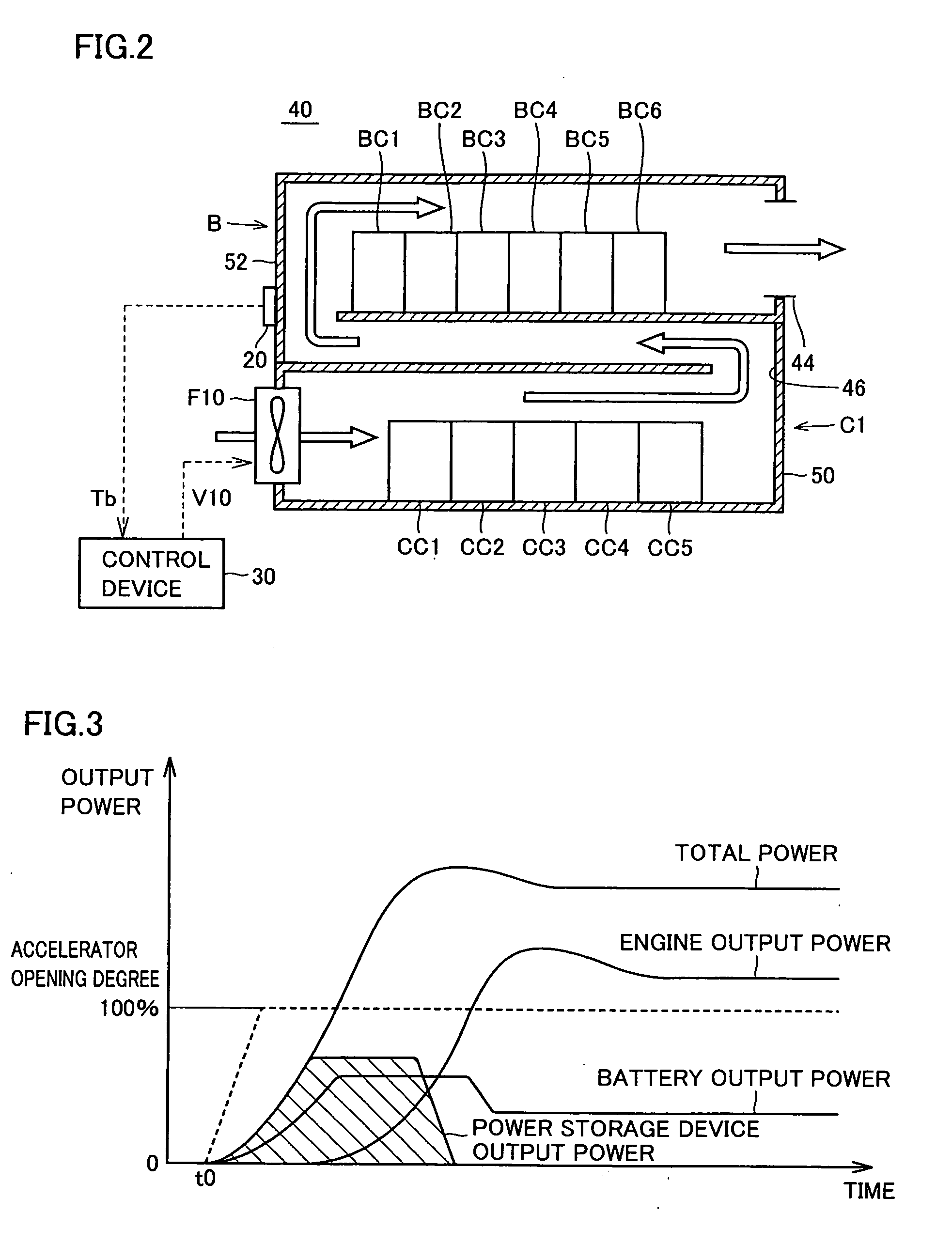
[0120]On the other hand, under low temperature circumstances, a reduction in the temperature of power storage device C1 may cause a reduction in the chargeable / dischargeable electric power of power storage device C1. In this case, quick electric power supply from power storage device C1 becomes impossible, deteriorating acceleration characteristic of a hybrid vehicle.

[0121]Therefore, under low temperature circumstances such as in a cold region, degradation in charge / discharge characteristic can be suppressed by employing a cooling structure shown in FIG. 6 in cooling ...

third embodiment

[0135]FIG. 7 is an overall configuration diagram of a cooling device in accordance with a third embodiment of the present invention.

[0136]Referring to FIG. 7, a cooling device 40C includes a cooling fan F1 placed in power storage device C1, a cooling fan F2 placed in battery B, and a cooling wind flow path for allowing cooling wind supplied from cooling fans F1 and F2 to flow therethrough.

[0137]Specifically, power storage device C1 has a structure in which casing 50 as an outer packaging member houses a plurality of capacitor cells CC1-CC5 stacked inside casing 50. The plurality of capacitor cells CC1-CC5 have basically the same structure, and are electrically connected in series. A gap as the cooling wind flow path is formed between the upper and lower surfaces of capacitor cells CC1-CC5 and casing 50, and between the stacked capacitor cells, to allow the cooling wind to flow therethrough.

[0138]Battery B has a structure in which casing 52 as an outer packaging member houses a plura...


PUM

PropertyMeasurementUnit
electric poweraaaaaaaaaa
heataaaaaaaaaa
distanceaaaaaaaaaa

Abstract

A cooling device includes a cooling fan placed in a power storage device, an exhaust port placed in a battery, and a cooling wind flow path for allowing cooling wind taken in from the cooling fan to flow therethrough. In the power storage device and the battery, communication between a gap inside a casing a gap inside a casing can be established via an opening. The cooling wind supplied from the wind blowing fan (F10) flows through the gap formed inside the casing for the power storage device to cool capacitor cells. Subsequently, the cooling wind that has passed through the power storage device is introduced into the inside of the casing for the battery via the opening, and flows through a gap between the upper surface of battery cells and the casing and a gap between the battery cells to cool the battery cells. Thereafter, the cooling wind is emitted to the outside of the casing via the exhaust port.

Description

TECHNICAL FIELD[0001]The present invention relates to a power supply unit, and in particular, to a power supply unit capable of supplying electric power from a secondary cell and a capacitor.BACKGROUND ART[0002]In recent years, hybrid vehicles and electric vehicles have been attracting attention as environmentally-friendly vehicles. A hybrid vehicle is a vehicle powered by a direct current (DC) power supply, an inverter, and a motor driven by the inverter, in addition to a conventional engine. Specifically, the hybrid vehicle is powered by driving the engine, and is also powered by converting DC voltage from the DC power supply by the inverter into alternating current (AC) voltage and rotating the motor by the converted AC voltage.[0003]Additionally, an electric vehicle is a vehicle powered by a DC power supply, an inverter, and a motor driven by the inverter.[0004]In such a hybrid vehicle or an electric vehicle, to improve energy efficiency while allowing the vehicle to run appropr...

Claims


Application Information

Patent Timeline
Patent Type & Authority Applications(United States)
IPC IPC(8): H05K7/20H01G2/08B60K6/28B60K6/445B60W10/26B60W10/30B60W20/00H01M10/60H01M50/204H01M50/249H02M7/48
CPCB60K1/02Y02T90/34B60K6/445B60K2001/005B60L3/003B60L3/0046B60L3/0053B60L11/1874B60L11/1879B60L11/1881B60L11/1892B60L11/1894B60L15/007B60L2240/36H01M2/1077H01M10/486H01M10/5004H01M10/5016H01M10/5022H01M10/5071H01M10/5073H01M10/5097H01M16/00H05K7/20909Y02T10/6239Y02T10/705Y02T90/16B60K6/365H01M10/667H01M10/613H01M10/625H01M10/633H01M10/6565H01M10/6566B60L58/30B60L58/26B60L50/64B60L58/34B60L58/33H01M50/249H01M50/204Y02T10/62Y02T10/64Y02T10/70Y02T90/40Y02E60/10B60Y2200/91B60Y2200/92
Inventor SOMA, TAKAYAYOSHIDA, HIROSHIMOGARI, TAKESHI
Owner TOYOTA JIDOSHA KK
Why Eureka
Try Eureka