Battery system cooled via coolant

a battery system and coolant technology, applied in the field of battery systems, can solve the problems of increased noise, additional drawbacks, and difficulty in rapid air-cooling batteries generating considerable amounts of hea

Inactive Publication Date: 2009-06-04
SANYO ELECTRIC CO LTD
View PDF14 Cites 91 Cited by
  • Summary
  • Abstract
  • Description
  • Claims
  • Application Information

AI Technical Summary

Benefits of technology

[0017]In the configuration above, the contact area between the cooling pipe and the surface plate is increased, and the cooling pipe and surface plate can be thermally joined in a preferable arrangement. Furthermore, the cooling plate hollow region is filled with plastic foam while cooling pipe flat sections are in close contact with the surface plate. Close contact between the cooling pipe and surface plate can be made even more reliable due to the plastic foam.

Problems solved by technology

Because of the low heat capacity of air, it is difficult to rapidly air-cool batteries generating considerable amounts of heat.
Further, if the amount of ventilation is increased to increase forced air-cooling, it has the additional drawback that noise levels increase.
Finally, a forced air-cooling system also has the detrimental effect that dust included in the air deposits inside the system to reduce cooling efficiency over time.
Although this system can efficiently cool rectangular batteries with cooling water, it requires a network of cooling pipe disposed between rectangular batteries.
Arrangement of cooling pipe in a battery system having many stacked rectangular batteries is extremely complicated.
However, in addition to the large heat capacity of this cooling plate, there is large thermal resistance between the coolant and the batteries, and rapid, efficient battery cooling is difficult to attain.
Time is required to cool the large heat capacity cooling plate itself, and batteries that have risen in temperature cannot be quickly cooled.
However, since this ideal configuration requires a unique arrangement of coolant and batteries, it cannot be practically adopted except for special applications.
However, in this configuration, if thermal contact between the cooling pipe and the surface plate is poor, coolant will not be able to efficiently cool the batteries.
Further, if the cooling pipe absorbs heat from elements other than the batteries, it will reduce the thermal efficiency of the coolant.

Method used


Image

  • Battery system cooled via coolant
  • Battery system cooled via coolant
  • Battery system cooled via coolant

Examples


Embodiment Construction

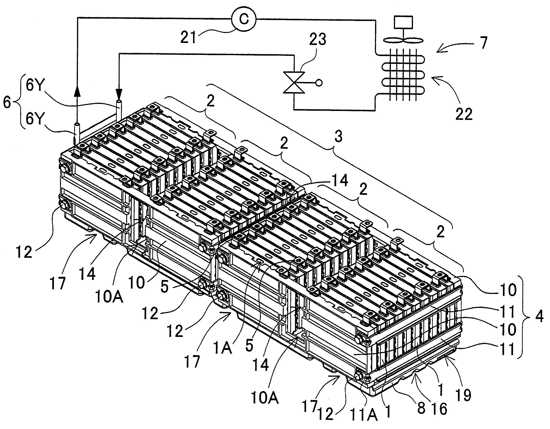
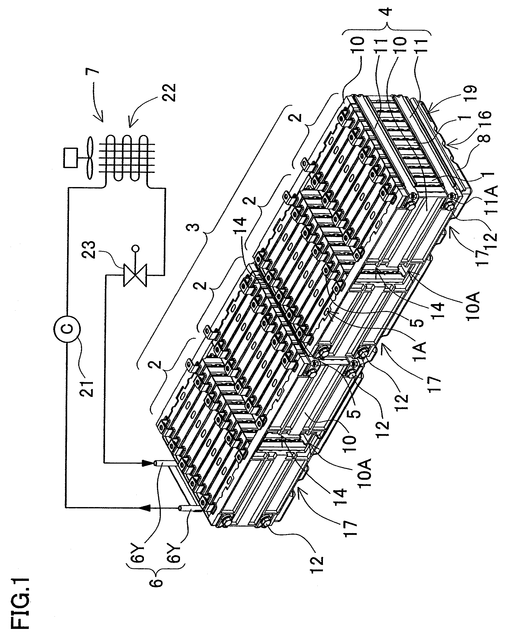
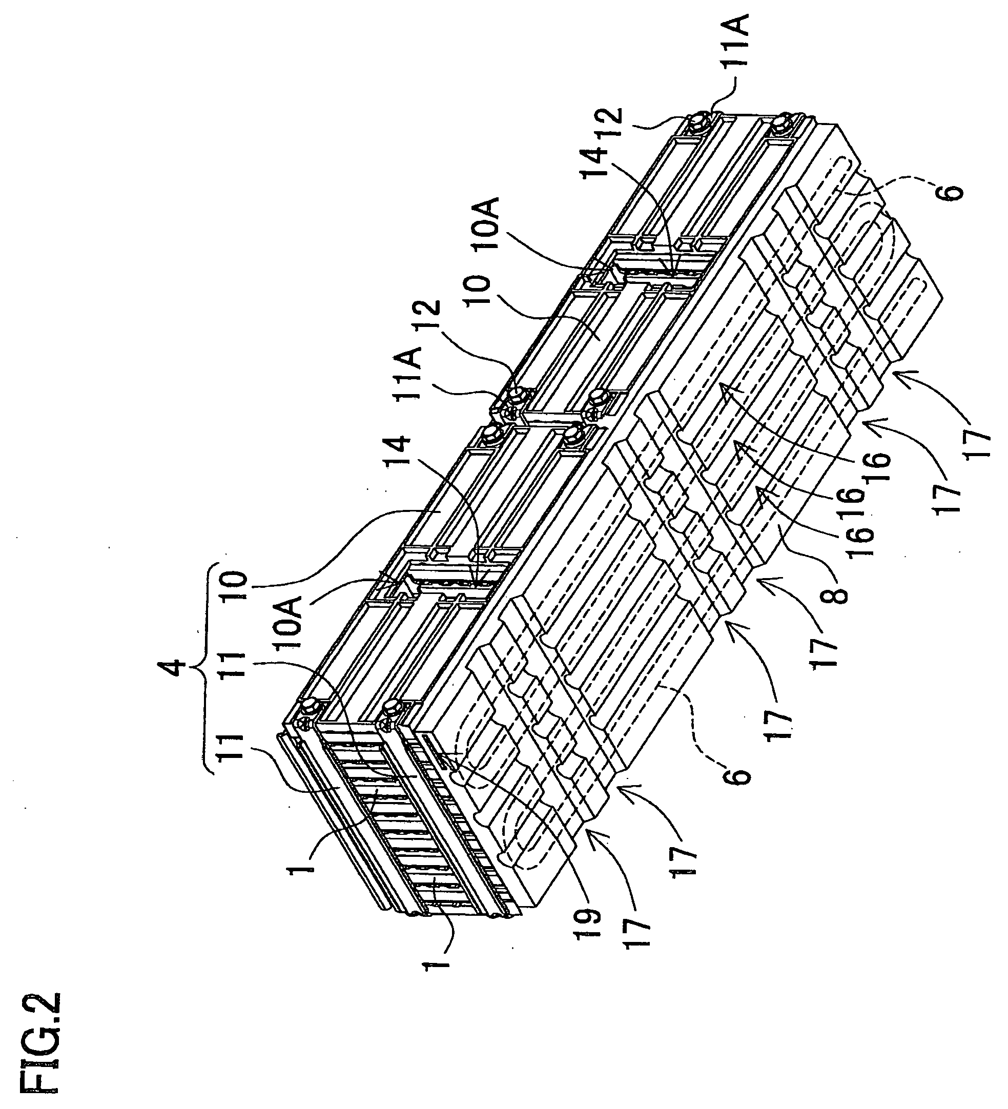
[0026]FIGS. 1-6 show a first embodiment and FIGS. 7 and 8 show a second embodiment of the present invention. The battery system shown in these figures is most suitable as a power source primarily for an electrically powered vehicle such as a hybrid car, which is driven by both an engine and an electric motor, or an electric automobile, which is driven by only an electric motor. However, the present invention can be used in vehicles other than a hybrid car or electric automobile, and it can also be used in applications that require large output other than electrically powered vehicles.

[0027]The battery systems of the following embodiments are provided with a battery block 3, 33 having a plurality of rectangular batteries 1, 31 that are wider than they are thick connected in a stacked configuration by a battery holder 4, 34; a cooling plate 8, 38 disposed in thermal contact with the bottom surface of the battery block 3, 33 and having a hollow region 18, 48 inside; cooling pipe 6, 36 ...


PUM

PropertyMeasurementUnit
shapeaaaaaaaaaa
electrically insulatedaaaaaaaaaa
output voltagesaaaaaaaaaa

Abstract

The battery system cooled via coolant has a battery block 3 with a plurality of rectangular batteries 1 retained in a stacked configuration by a battery holder 4; a cooling plate 8 disposed in thermal contact with the bottom surface of the battery block 3 and having a hollow region 18 inside; cooling pipe 6 disposed inside the hollow region 18 of the cooling plate 8; and a coolant supply device 7 to supply coolant to the cooling pipe 6. The hollow cooling plate 8 has a surface plate 8A that makes thermal contact with the bottom surface of the battery block 3, and cooling pipe 6 is disposed within the hollow region 18 in contact with the inside of the surface plate 8A. Further, the cooling plate 8 hollow region 18 is filled with plastic foam 9.

Description

BACKGROUND OF THE INVENTION[0001]1. Field of the Invention[0002]The present invention relates to a battery system having a battery block with a plurality of stacked rectangular batteries joined together and cooled via a coolant, and in particular relates to a battery system best suited as a power source for automobile applications such as in a hybrid car.[0003]2. Description of the Related Art[0004]A battery system provided with many rectangular batteries can produce higher output voltages and charge and discharge with high currents. In particular, a battery system used as a power source unit for an automobile is discharged at high currents during vehicle acceleration and is charged with high currents under conditions such as regenerative braking. Because temperature rises for a battery system charged and discharged with high currents, forced cooling is implemented via air or coolant. Because of the low heat capacity of air, it is difficult to rapidly air-cool batteries generating c...

Claims


Application Information

Patent Timeline
Patent Type & Authority Applications(United States)
IPC IPC(8): H01M2/00H01M10/60H01M10/613H01M10/625H01M10/647H01M10/653H01M10/6554H01M10/6555H01M10/6556H01M10/6563H01M10/6568H01M10/6569H01M10/658H01M50/103H01M50/119H01M50/209H01M50/291H01M50/293
CPCH01M2/0237Y02T10/7011H01M2/1077H01M2/1094H01M10/052H01M10/345H01M10/5004H01M10/5016H01M10/5032H01M10/5055H01M10/5057H01M10/5065H01M10/5077H01M10/5079Y02E60/122Y02E60/124H01M2/0285H01M10/625H01M10/647H01M10/6556H01M10/6568H01M10/6569H01M10/6555H01M10/613H01M10/6562Y02E60/10H01M50/24H01M50/293H01M50/209H01M50/103H01M50/291H01M50/119Y02T10/70
Inventor OKADA, WATARUSHIMIZU, HIDEONAKAMURA, SHINSUKE
Owner SANYO ELECTRIC CO LTD
Why Eureka
Try Eureka