
Sanitary spiral wound filtration cartridge

Active Publication Date: 2009-06-11
MANNHUMMEL WATER & FLUID SOLUTIONS GMBH
View PDF17 Cites 18 Cited by
  • Summary
  • Abstract
  • Description
  • Claims
  • Application Information

AI Technical Summary

Benefits of technology

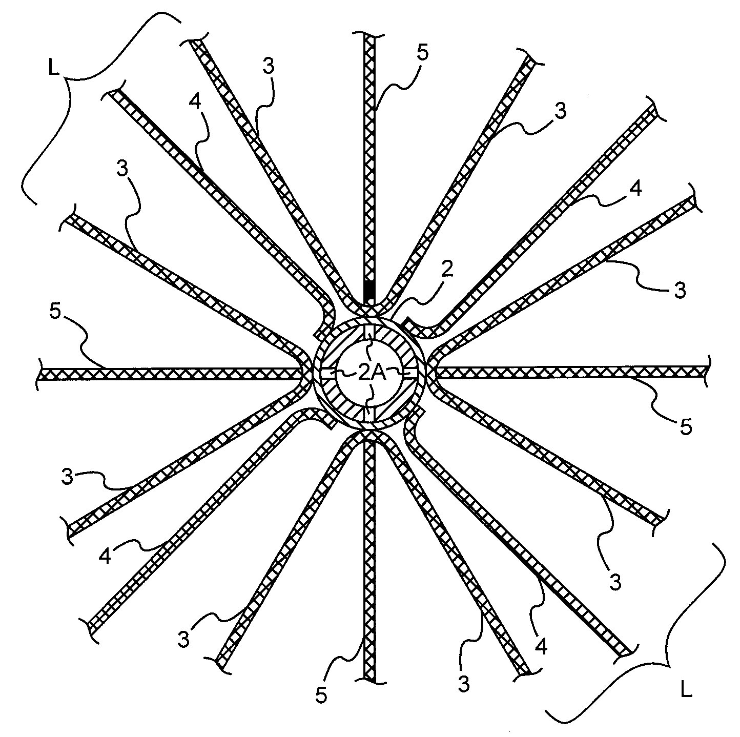
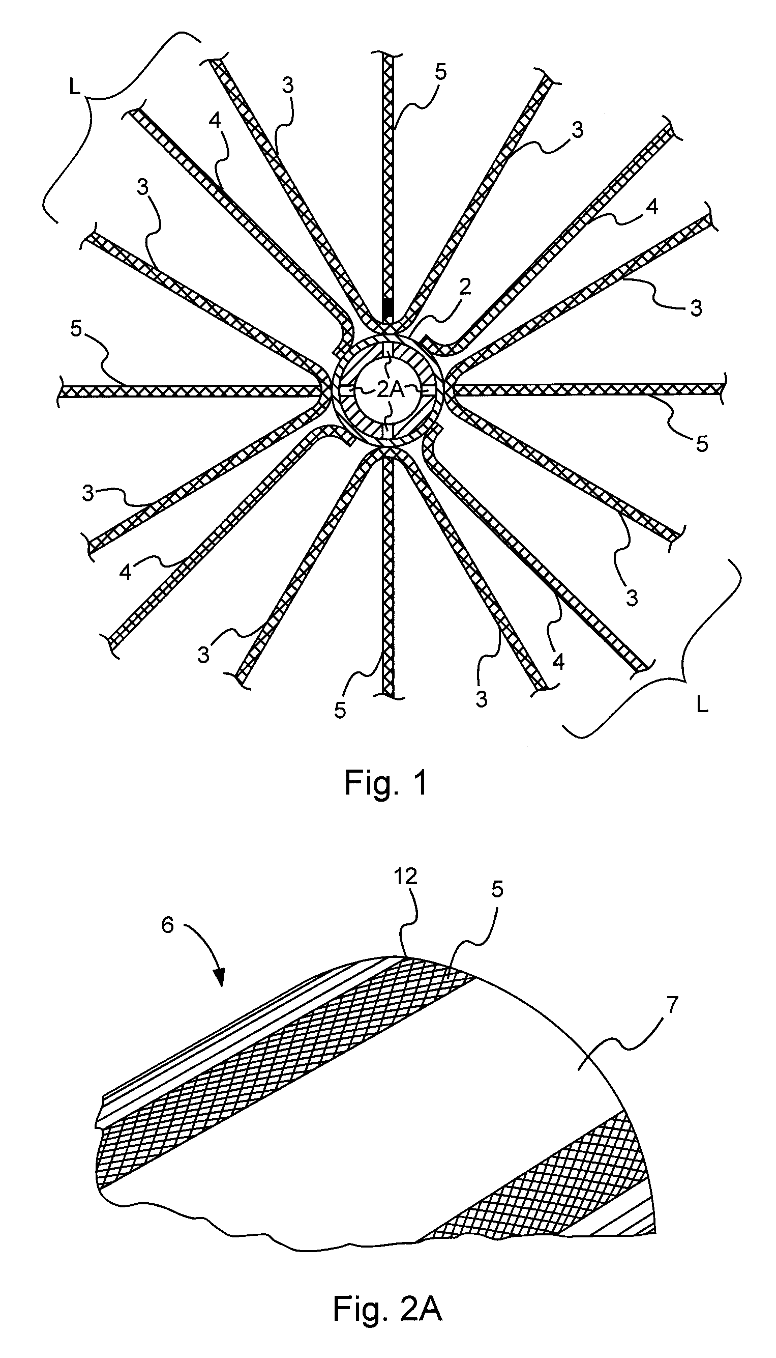
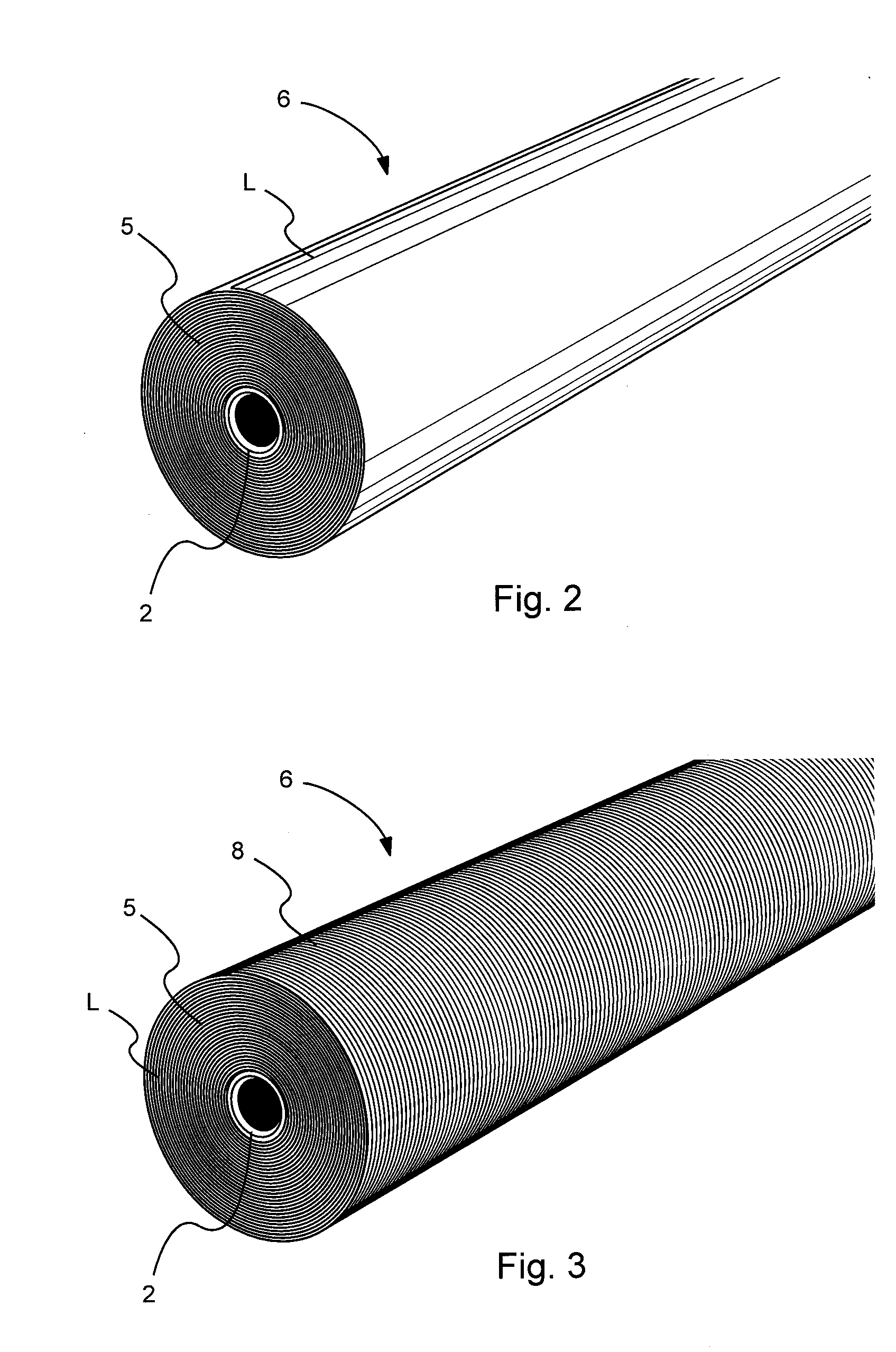
[0007]It has now been found that if, as a part of such a rewinding operation, an overwrap sheet of particular design is incorporated, it will not only facilitate rewinding so as to create a substantially cylindrical element with an outer diameter (OD) within very close tolerances that will then be snugly received within the thin outer shell to complete the cartridge, but that the character of the overwrap sheet employed can be such as to itself deter bypass flow of liquid feed through the cartridge in the region immediately interior of the shell surface. Moreover, when such rewinding is done utilizing a machine that is designed to tension or tighten the element to achieve a specific value during this operation, the result is a robust element construction that is capable of withstanding high differential pressures at high temperatures without telescoping.
[0020]The element is then inserted into the rigid shell to complete fabrication of the sanitary cartridge. The tight tolerance between the outside diameter of the element and the inside diameter of the shell, preferably between +0.050 in (1.3 mm) to −0.050 in (1.3 mm) diametrical clearance, insures that the element will not easily slide out of the shell or be capable of expanding inside the rigid shell. Its radial compression creates a cartridge that effectively resists telescoping.
[0024]In a further particular aspect, the invention provides a method of making a spiral wound membrane cartridge, which method comprises the steps of providing a central permeate collection tube and a plurality of sheets of feed spacer material, permeate carrier material, and semipermeable membrane filtration material, said membrane filtration material sheets having a length about twice as long as said other sheets and being folded approximately in half, adhesively attaching each of said permeate spacer sheets between half-sheets of two different semipermeable membrane filtration sheets with bands of adhesive which extend along both longitudinal side edges of said permeate carrier sheet and across the free end edge thereof and create 3-ply leaves, disposing a feed spacer sheet between each two facing half-sheets of filtration membrane material, spirally wrapping said plurality of sheets about said central permeate collection tube with a tension of at least 1.7 lbf / in (300 N / m) to provide an assemblage of sheets in radial compression, and associating a thin tubular shell having textured exterior surface with said tensioned assemblage to provide a filtration cartridge which allows a controlled bypass flow of liquid feed between a pressure vessel interior surface and said textured exterior surface of said shell.

Problems solved by technology

The presence of seals, between the exterior surface of such a spirally wound element and the interior of a pressure vessel, within which it is normally operated, creates difficulties in assuring that cleaning is adequately carried out to prevent potential bacterial growth in such regions.
If there is a rather loose-fitting arrangement, there will be additional bypass along the interior surface of the shell until such time as the assemblage slowly radially expands; however, such expansion will very likely result in the creation of some relatively open passageways directly through the element and thereby result in a potential decrease in performance.
Another concern is the potential extrusion of the feed spacer sheeting, known as telescoping, that can result from high differential feed-brine pressures; such can abrade the membrane surface and result in shortened membrane life.
It is also possible that, after an element has been in service for a long period of time, the combination of pressurization cycles and fluctuations in temperature can cause compression of the thickness of the membrane material and / or the permeate carrier fabric.
Such can result in an enlarged space between the element and the inside of the shell which can lead to the element slipping out of its shell during subsequent cartridge unloading and / or repositioning in the pressure vessel.
Because in a production line operation it is not possible to position the crosswise band of adhesive that creates the end seal precisely at the end of all three of the two membrane sheets and the permeate carrier sheet being sandwiched therebetween, there will nearly always be short edge regions of the three sheets that may extend past the crosswise adhesive band.

Method used


Image

  • Sanitary spiral wound filtration cartridge
  • Sanitary spiral wound filtration cartridge
  • Sanitary spiral wound filtration cartridge

Examples


example 1

[0056]A 6.3 in (160 mm) diameter by 40 in (1 m) long element was rolled using 12 folded leaves of TriSep UE10 polyethersulfone ultrafiltration membrane, 12 leaves of Delstar 0.031 in (0.79 mm) thick with 9 strands per inch (3.5 strands per cm) style 14592 feed spacer, and 12 leaves of 0.012 in (0.30 mm) thick epoxy-coated tricot permeate carrier sheeting. Winding is carried out around a polysulfone permeate tube with an OD of about 1.68 in (42.7 mm), and a two part polyurethane adhesive is used for the side and end seals. The wound element was secured using adhesive tape. After allowing the urethane adhesive to cure for 12 hours, the element was placed onto a tensioning machine as depicted in FIG. 6. The end seals were trimmed, and then the end of a roll of overwrap sheet material was attached using a thermal sealer. The overwrap material is a polypropylene netting material with a thickness of 0.031 in (0.79 mm). The element was tensioned to 5.6 lbf / in (1,000N / m) while winding seven...

example 2

[0057]Two 7.9 in (201 mm) diameter by 40 in (1 m) long elements were rolled using 18 folded leaves of TriSep ACM2 polyamide reverse osmosis membrane, 18 leaves of Delstar 0.031 in (0.79 mm) thick with 9 strands per inch (3.5 strands per cm) style 14592 feed spacer, and 18 leaves of 0.012 in (0.30 mm) thick epoxy-coated tricot permeate carrier. A polysulfone permeate tube with an OD of about 1.68 in (42.7 mm) and a two-part polyurethane adhesive were used. The wound elements were secured using adhesive tape.

[0058]After allowing the urethane adhesive to cure for 12 hours, one element was placed onto a tensioning machine as seen in FIG. 6. The end seals were trimmed, and then overwrap sheeting was attached using a thermal sealer as in Example 1. The overwrap material was a woven fabric which was made from polypropylene and had a thickness of 0.031 in (0.79 mm). The element was tensioned to 6.2 lbf / in (1,100N / m), while winding five complete wraps of overwrap sheet around the outside of ...

example 3

[0061]Two 7.9 in (201 mm) diameter by 40 in (1 m) long elements were rolled using 18 folded leaves of TriSep ACM2 polyamide reverse osmosis membrane, 18 leaves of Delstar 0.031 in (0.79 mm) thick, with 9 strands per inch (3.5 strands per cm) style 14592 feed spacer, and 18 leaves of 0.012 in (0.30 mm) thick epoxy-coated tricot permeate material. A polysulfone permeate tube of OD about 1.68 in (42.7 mm) in and a two-part polyurethane adhesive were used. The wound elements were secured using adhesive tape. After allowing the urethane adhesive to cure for 12 hours, one element was placed onto the tensioning machine of FIG. 6. The end seals were trimmed, and then an overwrap sheeting was attached using a thermal sealer as in Example 1. The overwrap sheeting was a polyproylene netting material with a thickness of 0.031 in (0.78 mm). The element was tensioned to 7.0 lbf / in (1,250N / m) while winding seven complete wraps of overwrap sheet around the outside of the element. The sheeting was t...


PUM

PropertyMeasurementUnit
Lengthaaaaaaaaaa
Lengthaaaaaaaaaa
Lengthaaaaaaaaaa

Abstract

Sanitary elements and cartridges of high performance are described which utilize a thin surrounding tubular shell with an exterior textured surface. Through the use of an overwrap material of particular design and by wrapping an assemblage of sheets of semipermeable membrane material, permeate carrier material and feed spacer material using a high tension, a spirally wound crossflow filtration element is constructed which has a substantially cylindrical outer surface of closely controlled OD that smoothly fits within such shell and which resists telescoping as a result of its radial compression.

Description

CROSS REFERENCE TO RELATED APPLICATIONS[0001]This application claims priority from U.S. provisional application Ser. No. 60 / 992,494, filed Dec. 5, 2007, the disclosure of which is incorporated herein by reference.[0002]This application relates generally to spiral wound filtration elements made of sheetlike semipermeable membrane material designed for crossflow filtration operation, and more particularly to cartridges incorporating such sanitary elements wherein a controlled bypass of the liquid feed is afforded exterior of the spirally wound element.BACKGROUND OF THE INVENTION[0003]When spiral wound filtration elements are used in the dairy industry and other food industries, as well as in the pharmaceutical industry, regulations are such that they must regularly be sanitized by flushing with cleaning solutions. The presence of seals, between the exterior surface of such a spirally wound element and the interior of a pressure vessel, within which it is normally operated, creates dif...

Claims


Application Information

Patent Timeline
IPC IPC(8): B01D63/10B01D67/00
CPCB01D63/10B01D2323/42B01D2313/04B01D63/107B01D2313/042B01D2313/041
Inventor KNAPPE, PETER H.TANNER, MATTHEW
Owner MANNHUMMEL WATER & FLUID SOLUTIONS GMBH
Learn More